PMNT piezoelectric transducer for ultrasonic deicing

A piezoelectric transducer and ultrasonic technology, which is applied in the direction of fluid using vibration, etc., can solve the problems of unsuitability for assembly and deicing, the total weight of the transducer is large, and the volume of the front mass block is large. The effect of high processing and working frequency

Pending Publication Date: 2019-02-22
BEIHANG UNIV
0 Cites 3 Cited by

AI-Extracted Technical Summary

Problems solved by technology

Although the generally used sandwich-type thickness vibration transducer has stable output and large power capacity, in order to increase the front-to-back vibration velocity ratio during design, a rear mass bl...

Method used

Piezoelectric sheet 2 often determines the power of transducer, for obtaining better deicing effect, the material of piezoelectric sheet 2 selects PMNT piezoelectric material for use, and the piezoelectric coefficient of this material can reach 1500-2000pC/N , is 6.5 times that of the traditional PZT-4 piezoelectric ceramic material, the electromechanical coupling coefficient is above 0.9, and the strain amount reaches 1.7%. Piezoelectric coefficient, electromechanical conversion efficiency and strain have great advantages; for transducers with large radial dimensions, setting the diameter of the piezoelectric ceramic element to be less than 1/4 of the wavelength of the acoustic wave can avoid longitudinal resonance of the transducer The frequency is coupled with the radial vibration of other components to ensure the efficiency of the transducer. Therefore, the outer radius R1 of the piezoelectric sheet 2 is set to 13mm-16mm. The inner radius r1 is slightly larger than the radius of the screw 71 in order to avoid electrical conduction or friction caused by contact with the bolt 7, and the value is 3.6mm-3.8mm, and the thickness m1 of the piezoelectric sheet is 2.9mm-3.1mm.
The cross-sectional dimension of prestressing screw 71 is selected as 1/4 to 1/3 of piezoelectric sheet 2 outer radius, and is slightly smaller than piezoelectric sheet 2 inner radius, guarantees that bolt 7 is in piezoelectric sheet 2 vibration process Mechanical strength. And if it can be realized, the finer the pitch, the better. The finer the pitch, it means that the prestress of the bolt 7 will be more uniform, and the mechanical properties will be better. At the same time, the fine-pitch screw 72 can better control the loading of the pre-tightening force, and can ensure that the pre-tightening force between the piezoelectric sheet 2 and the metal cover plate is more uniform, and such a stress effect can bring the whole transducer Higher mechanical quality factor and lower mechanical loss at the same time. Combined with the thread standard, the pitch of the external thread of the screw and the screw is set to 0.3mm-0.5mm.
Therefore, the power of the designed transducer is found to be 125.5W, which is higher than the power (60W) of the general PZT-4 transducer. On the one hand, the dielectric properties of the piezoelectric materials used are different, the piezoelectric The size of the film is different, and on the other hand, it is also related to its operating frequency. The transducer designed in the present invention adopts PMNT piezoelectric material, selects thinner piezoelectric sheet, and the working frequency is also higher, so the power will become larger. The high-power transducer means higher power density, and the use of aircraft deicing means that the deicing ta...

Abstract

The invention discloses a PMNT piezoelectric transducer for ultrasonic deicing. The piezoelectric transducer is provided with a back cover plate, two piezoelectric chips and front gaskets in turn fromtop to bottom, wherein electrode chips are arranged between the back cover plate and the piezoelectric chip, between the two piezoelectric chips, and between the piezoelectric chip and the front gasket, a base is arranged at the center of the front gasket, concentric round holes are arranged on the back cover plate, the piezoelectric chips, the electrode chips and the base, and each concentric round hole is connected to another hole to form a connecting channel, a bolt is arranged in the connecting channel, a shell is fixed on the back cover plate, and the shell is circumferentially arrangedon the outer sides of the piezoelectric plates and the electrode plates. The PMNT piezoelectric transducer has the advantages of stable output, large power capacity, small size, light weight, easy installation and so on and the PMNT piezoelectric transducer is suitable for being mounted on a plane to deice.

Application Domain

Mechanical vibrations separation

Technology Topic

EngineeringTransducer +3

Image

  • PMNT piezoelectric transducer for ultrasonic deicing
  • PMNT piezoelectric transducer for ultrasonic deicing
  • PMNT piezoelectric transducer for ultrasonic deicing

Examples

  • Experimental program(1)

Example Embodiment

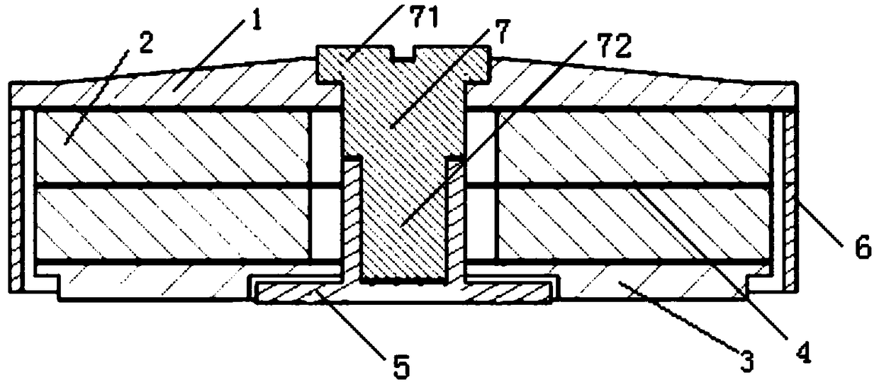
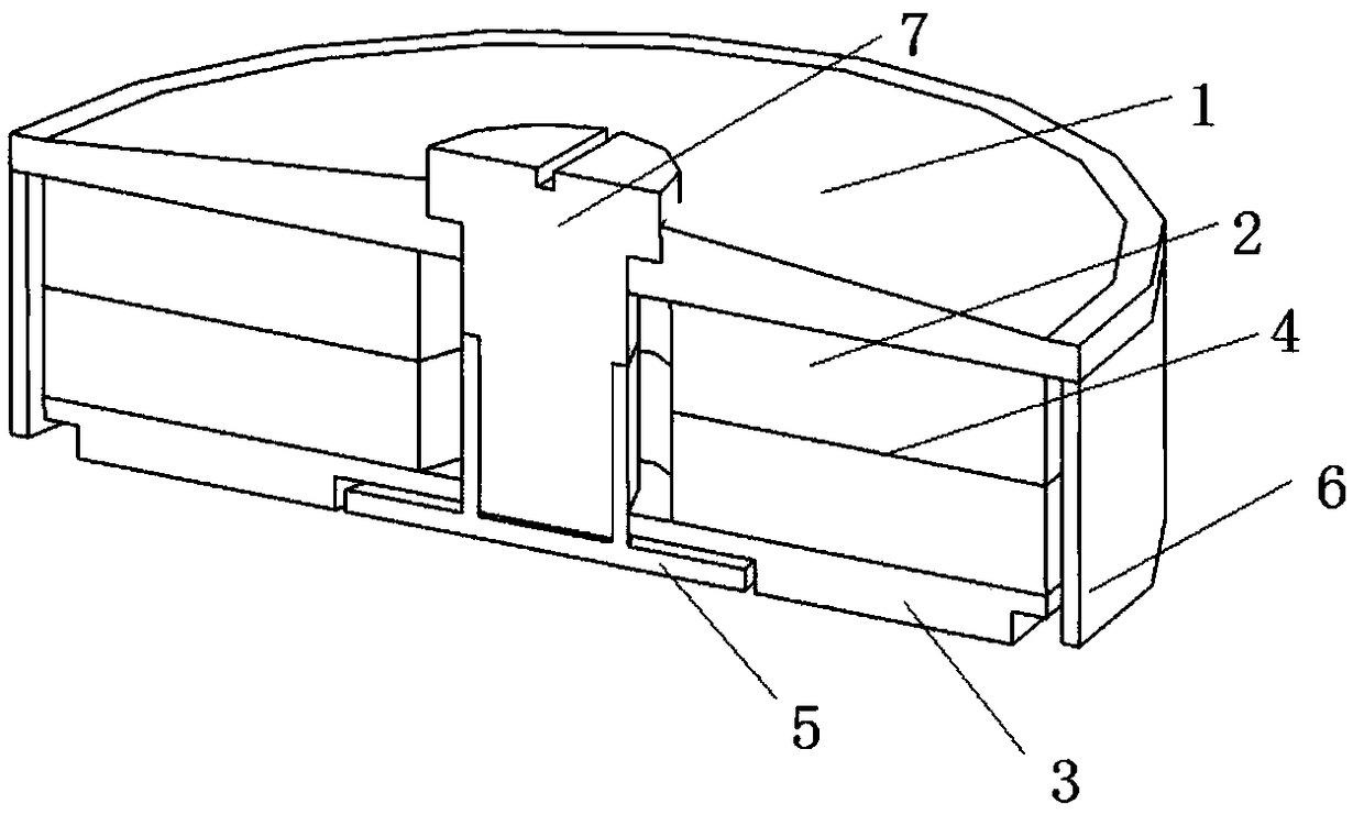
[0044] Embodiment 1: The transducer includes a back cover 1, a piezoelectric sheet 2, a front gasket 3, an electrode sheet 4, a circular base 5, a housing 6, a bolt 7 and other components, and two piezoelectric sheets 2 of the same thickness There are electrode sheets 4 between them. Two piezoelectric sheets 2 are connected to the front gasket 3 and the rear cover 1 respectively. There is a circular base 5 in the middle of the front gasket 3, and a shell 6 is glued and fixed on the circular base 5. The two piezoelectric sheets 2 and the electrode sheet 4 are surrounded by a shell 6. The back cover 1, the piezoelectric sheet 2, the electrode sheet 4, and the circular base 5 are all provided with concentric circular holes, and each concentric circular hole is connected to form a connecting channel , There are prestressed adjusting bolts in the connecting channel.
[0045] Attached Figure 4 As shown, the total thickness m of the transducer is 10.4 mm, and the outer radius of the transducer is R 2 It is 16 mm. The thickest thickness of the back cover 1 is 2 mm, and its rigidity is strengthened by four ribs; the thickness of the two piezoelectric sheets 2 m 1 The same, both are 3mm, and use PMNT piezoelectric material, the outer radius of the piezoelectric sheet 2 is R 1 15mm, inner radius r 1 3.8mm; the outer radius and inner radius of the front gasket 3 are equal to the piezoelectric sheet 2, respectively 15mm and 3.8mm; the electrode sheet 4 adopts a thickness of m 2 0.2mm brass, the brass between the two piezoelectric plates 2 is the positive electrode, the brass between the back cover plate 1 and the piezoelectric plate 2, and between the piezoelectric plate 2 and the front gasket 3 are all Negative electrode; base 5 radius r 3 6mm; the thickness of the shell 6 is m 3 0.5mm epoxy plastic; bolt 7 includes screw 71 and screw 72, where the radius of screw 71 is r 2 Set to the outer radius R of the piezoelectric sheet 2 1 1/4.
[0046] Use finite element simulation to verify whether the designed transducer can remove the ice on the back of the board. The plate ice model of the transducer of the present invention is simplified as necessary, and the simplified transducer and plate ice model are as Figure 5 Shown.
[0047] (1) Material properties
[0048] The material properties of PMNT piezoelectric ceramics are: material density: 8093kg/m 3 , PMNT dielectric constant matrix
[0049]
[0050] PMNT stiffness matrix
[0051]
[0052] PMNT piezoelectric matrix
[0053]
[0054] The dimensions of the aluminum plate and ice layer used to simulate the aircraft skin are both 300mm×210mm×2mm, and the material parameters are shown in Table 1.
[0055] Table 1 Properties of aluminum plate in icing material
[0056]
[0057] (2) Boundary conditions
[0058] The installation distance of the transducer on the board can be determined by the formula It is confirmed that d=150mm is taken here, and the bottom end of the base and the metal plate are bound by bonding. A voltage of 100V is applied to the interface between the two piezoelectric sheets while a voltage of 0V is applied to both ends. This means that when performing spectrum analysis, an alternating voltage is generated on the piezoelectric chip. The metal plate adopts four-sided fixed support to simulate the riveting form of the aircraft skin. The metal plate refers to a board that simulates the aircraft skin.
[0059] (3) Calculation and analysis
[0060] The resonance analysis of the entire deicing structure is performed first. In order to find the best deicing frequency, several points are randomly selected at the plate-ice interface, and the relationship between the XY shear stress and frequency is output, such as Image 6 Shown. It is not difficult to conclude from the figure that the best frequency for deicing is 92.0kHz under the excitation of this transducer.
[0061] Under the excitation of the optimal frequency of 92.0kHz, the shear stress at the plate-ice interface is distributed as Figure 7 Shown. According to the experimental data, the shear strength between ice accretion and aluminum plates with different roughness is between 0.15MPa and 0.4MPa in most cases. In order to make the research object more general, it is believed that the shear strength between the skinned aluminum sheet and the ice accretion is about 0.3MPa. It can be seen from the figure that the absolute value of the shear stress in most areas of the plate-ice interface is greater than 2MPa. Image 6 The maximum stresses of several randomly selected points are 2.93MPa, 4.12MPa, 10.12MPa, 8.76MPa. It can be concluded that the transducer can remove the ice on a given plate surface.
[0062] (4) Transducer power calculation
[0063] The current of the piezoelectric material of the transducer can be calculated by the following formula
[0064] I=2πf*C*V
[0065] Among them, C is the capacitance of the piezoelectric material itself, f is the frequency selected for deicing. From the above calculation and simulation, it can be concluded that the optimal frequency is 92.0kHz, and V is the peak voltage applied by the circuit, where the value is 141V. The capacitance of the piezoelectric sheet can be directly measured by experiment or can be determined by the following formula:
[0066] C=ε T ε 0 S/d
[0067] Where ε T Is the dielectric constant of the piezoelectric sheet, the value is 5569, ε 0 Is the vacuum dielectric constant of 8.85×10⁻¹²F/m, d is the thickness of the piezoelectric sheet, and the value is 3mm. S is the facing area of ​​the piezoelectric sheet, the value is 661mm 2 , It can be calculated that the capacitance of the piezoelectric sheet of the present invention is 10.9nF, and the current I is 0.89A.
[0068] Therefore, the power of the designed transducer is calculated to be 125.5W, which is higher than the power (60W) of the general PZT-4 transducer. In this respect, the dielectric properties of the piezoelectric materials used are different, and the size of the piezoelectric sheet Different, on the other hand, is also related to its operating frequency. The transducer designed by the present invention adopts PMNT piezoelectric material, chooses a thinner piezoelectric sheet, and has a higher working frequency, so the power will increase. High-power transducers mean higher power density. Used for aircraft deicing means that deicing tasks can be completed in a shorter time, or a larger area of ​​ice can be removed in the same time.
[0069] (5) Performance comparison analysis
[0070] The designed PMNT piezoelectric transducer is compared with the PZT sandwich transducer. Such as Figure 8 Shown. The right PZT sandwich transducer, which is now commonly used in ultrasonic cleaning, is simple to manufacture, inexpensive, and has excellent deicing performance. However, the transducer has a heavier structure and a relatively large volume. If it is used in actual aircraft deicing, it will add a larger mass to the aircraft. This will greatly limit its application in the aviation field. On the left is the PMNT piezoelectric transducer of the present invention. It can be seen from the performance analysis result that the transducer of the present invention can generate sufficient shear stress between the plate-ice interface, and therefore can also achieve the purpose of deicing. It can be seen from the structural diagram that the transducer of the present invention is much smaller in volume than the PZT, the maximum height and the maximum radius are significantly reduced, and the weight is also reduced, which is very important for the lightweight design of aviation. Moreover, since the transducer was redesigned, the requirements for ease of processing, ease of assembly, and ease of installation were considered, so it has a huge application prospect. The weight and size parameters of the two transducers are listed in Table 2.
[0071] Table 2 Comparison of structural parameters of PMNT piezoelectric transducer and PZT sandwich transducer
[0072]
[0073] It can be seen from the above comparison table that under the premise that the purpose of deicing can also be achieved, the weight of the designed PMNT piezoelectric transducer is only 13% of the PZT sandwich transducer, and the maximum height is less than 20%. The weight and volume are greatly reduced, but it can ensure the power required for deicing. For the entire aircraft, a large number of transducers are required for the deicing of the entire aircraft, so it is necessary to use transducers with high power density. The weight reduction effect of each transducer by more than 80% is of great significance for advancing the application of ultrasonic deicing technology.

PUM

PropertyMeasurementUnit
Thickness2.9 ~ 3.1mm
Outer radius13.0 ~ 16.0mm
Inner radius3.6 ~ 3.8mm

Description & Claims & Application Information

We can also present the details of the Description, Claims and Application information to help users get a comprehensive understanding of the technical details of the patent, such as background art, summary of invention, brief description of drawings, description of embodiments, and other original content. On the other hand, users can also determine the specific scope of protection of the technology through the list of claims; as well as understand the changes in the life cycle of the technology with the presentation of the patent timeline. Login to view more.

Similar technology patents

Classification and recommendation of technical efficacy words

  • light in mass
  • reduce loss

High-voltage line inspection robot

Owner:SHENZHEN JINGZHI MACHINE

Deployable surface device with fixed truss structure

InactiveCN102011922Alight in massLow areal density
Owner:XIDIAN UNIV

Aircraft with changeable wing shape

Owner:HARBIN INST OF TECH

Large-angle all-round-lighting LED bulb

InactiveCN103712106AOptimize space arrangementlight in mass
Owner:BONSHINE OPTICAL ELECTRON TECH
Why Eureka
Try Eureka