
High-speed milling cutter handle type electric spindle

A high-speed milling and electric spindle technology, which is applied to milling cutters, milling machine equipment, large fixed members, etc., can solve the problem that the radial machining accuracy and processing efficiency are difficult to guarantee at the same time, affect the working stability and service life of the electric spindle, and reduce the overall work Efficiency and spindle life and other issues, to achieve the effect of expanding the range of tool specifications, saving use and maintenance costs, strong adaptability and practicability

Pending Publication Date: 2019-02-22
岳阳市显隆电机有限公司
View PDF5 Cites 6 Cited by
  • Summary
  • Abstract
  • Description
  • Claims
  • Application Information

AI Technical Summary

Problems solved by technology

[0002] In the prior art, high-speed electric spindles generally adopt the principle of asynchronous motors, and use AC frequency conversion technology to change the current frequency and excitation voltage of the stator windings of the motor to obtain various speeds. However, in practical applications, the stator coil jacket is made of steel. Components, and there is no circulating cooling system to reduce the temperature of the spindle when it is running at high speed. When the electric spindle is working at high speed, the temperature rises faster and the iron loss of the motor is too high. Because it is in a high temperature state for a long time, it will affect the stability of the electric spindle. and service life, the rotor magnetic parts are made of die-casting aluminum, which generates heat obviously, which indirectly causes the stator coil to heat up, reduces the overall working efficiency and the life of the spindle, and increases the maintenance cost. The disadvantage of this clamping method is that the radial constraint and radial rigidity of the tool are small. When performing large-scale milling, it is difficult to achieve radial machining accuracy and machining efficiency at the same time. Guaranteed, the axial machining depth is limited, and at the same time, after a long time of high-intensity work on the spindle, the rotor shaft core and chuck will be worn to a certain extent, the use and maintenance costs are high, and the versatility is poor

Method used


Image

  • High-speed milling cutter handle type electric spindle
  • High-speed milling cutter handle type electric spindle
  • High-speed milling cutter handle type electric spindle

Examples


specific Embodiment approach

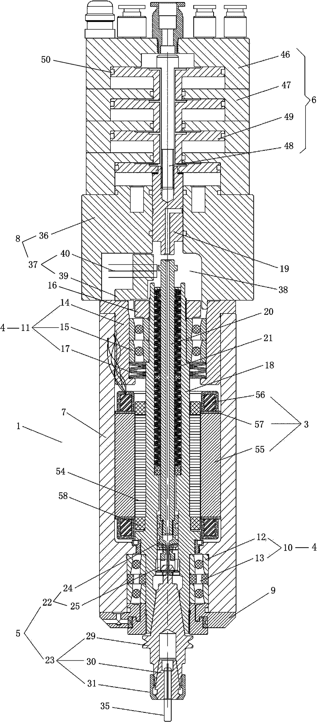
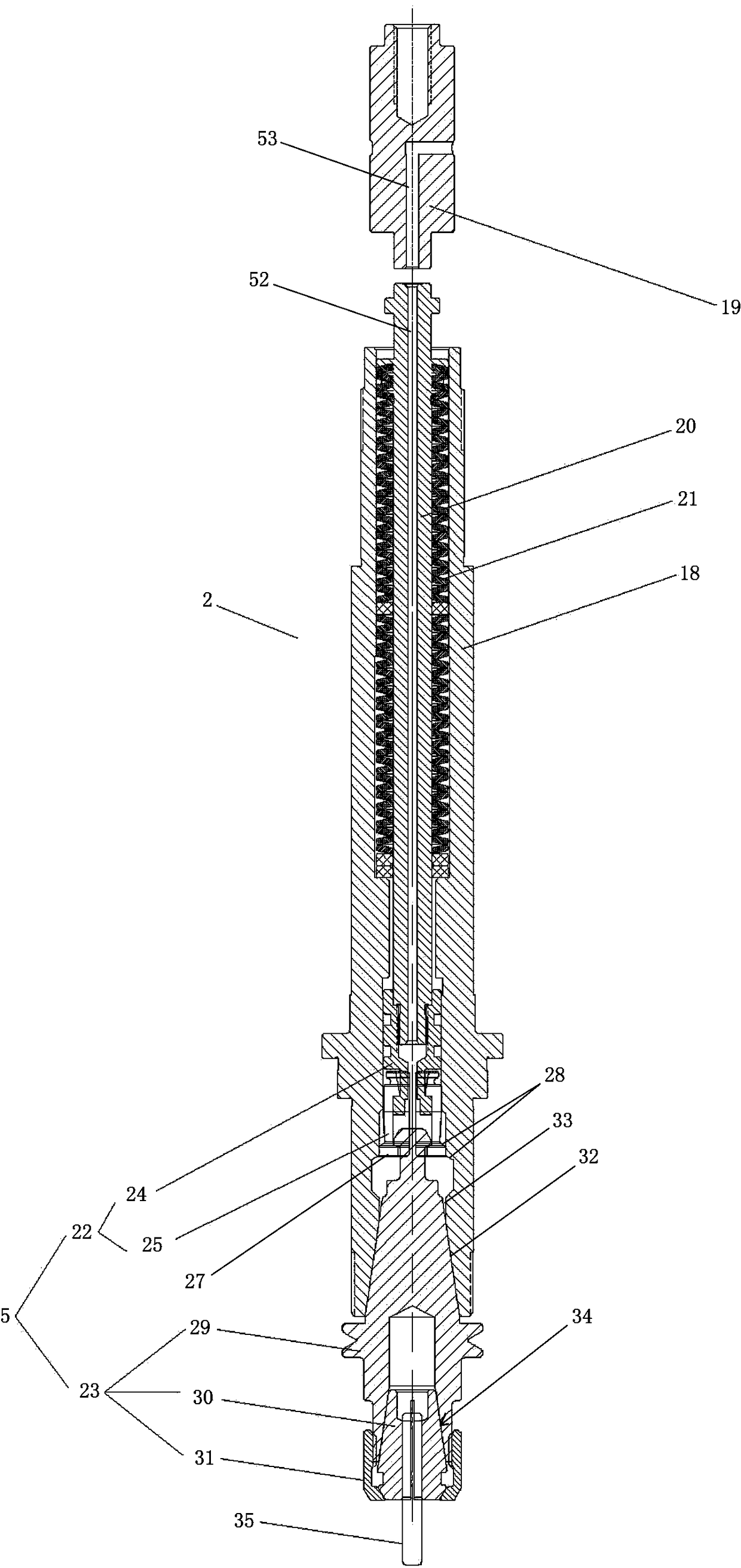
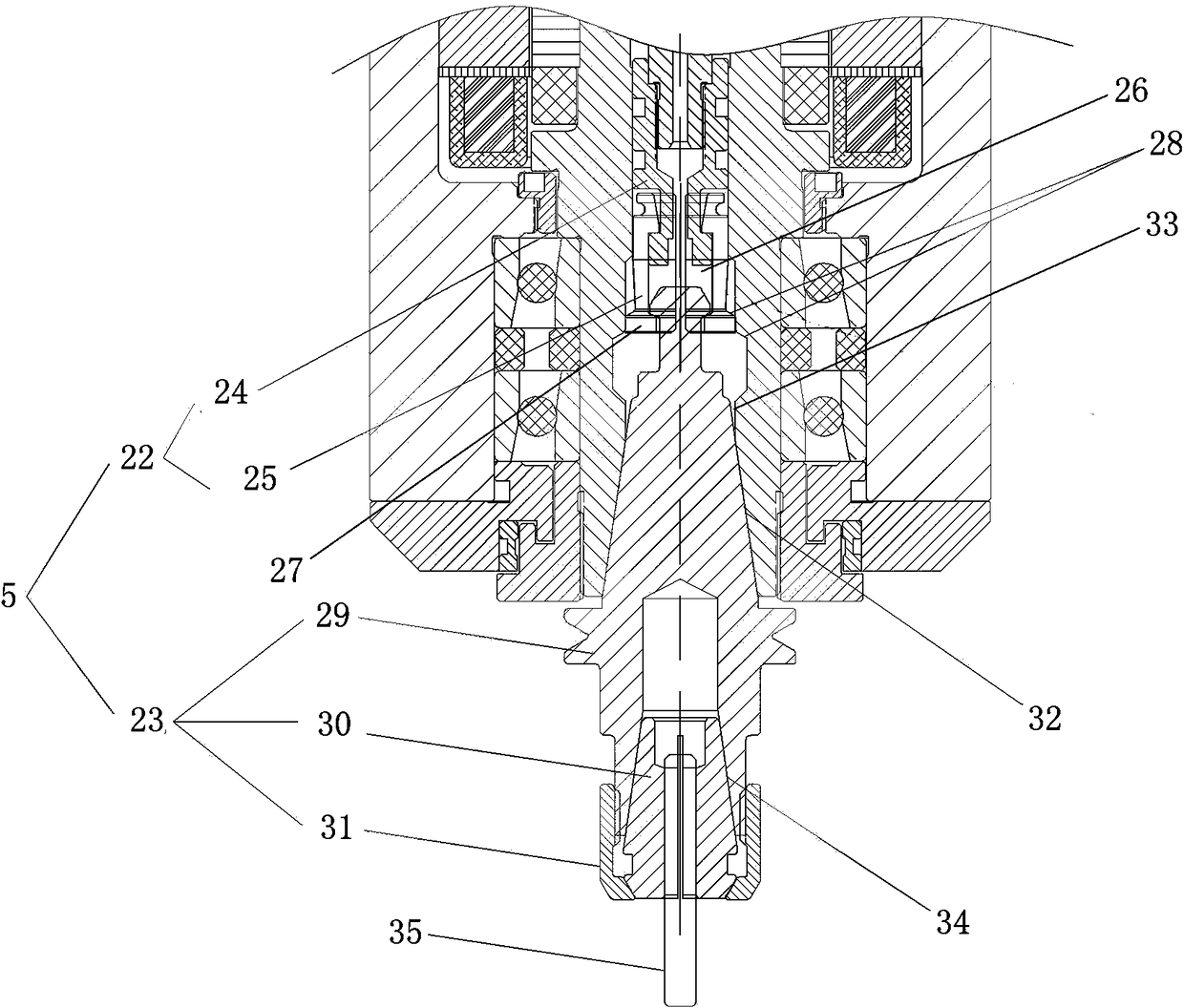
[0024] like Figure 1-5 As shown, a high-speed milling shank-type electric spindle includes a main body mechanism 1, a rotor mechanism 2, a stator mechanism 3, a bearing mechanism 4, a broach mechanism 5, and a cylinder mechanism 6. The main mechanism 1 includes a spindle housing 7, The rear seat mechanism 8 and the dust cover 9 respectively arranged at the two ends of the main shaft housing 7, the main body mechanism 1 and the rear seat mechanism 8 are all provided with cooling mechanisms, the rotor mechanism 2, the stator mechanism 3 and the The bearing mechanism 4 is respectively installed in the inner cavity of the spindle housing 7, the cylinder mechanism 6 is provided on the rear seat mechanism 8 to provide power, and the bearing mechanism 4 includes A front bearing assembly 10 and a rear bearing assembly 11 at both ends, the front bearing assembly 10 is composed of several front bearings 12, and inner and outer backing rings 13 are arranged between the several front bea...


PUM


Abstract

The invention relates to a high-speed milling cutter handle type electric spindle which comprises a main body mechanism, a rotor mechanism, a stator mechanism, a bearing mechanism, a broach mechanismand an air cylinder mechanism. The bearing mechanism comprises a front bearing assembly and a back bearing assembly arranged at two ends of the rotor mechanism; the front bearing assembly is providedwith an inner backing ring and an outer backing ring; a backing ring and an adjusting spring located in the same axis are arranged on the upper side and the lower side of the back bearing assembly; and the broach mechanism is detachably arranged on the rotor mechanism. The high-speed milling cutter handle type electric spindle provided by the invention has the beneficial effect that the electric spindle is provided with a position proximity switch connected with a programable logic controller (PLC) control center, so that a function on intelligently monitoring and automatically changing a cutter is realized. With an innovative self-designed cutter handle holding mechanism, the structural strength and the bearing surface are greatly increased, and the cutter holding force, the radial cutting rigidity and the loading force are further greatly improved, so that the high metal removal rate is achieved; and multi-process integrated processing of workpieces can be realized through a machinetool cutter rest, and a power assisting machine tool equipment manufacturer realizes high-intelligent automatic and integrated product functions.

Description

technical field [0001] The invention relates to an electric spindle, in particular to a high-speed milling tool handle electric spindle applied to light-duty precision engraving and milling machines and light-duty machining centers and other mechanical processing machines. Background technique [0002] In the prior art, high-speed electric spindles generally adopt the principle of asynchronous motors, and use AC frequency conversion technology to change the current frequency and excitation voltage of the stator windings of the motor to obtain various speeds. However, in practical applications, the stator coil jacket is made of steel. Components, and there is no circulating cooling system to reduce the temperature of the spindle when it is running at high speed. When the electric spindle is working at high speed, the temperature rises faster and the iron loss of the motor is too high. Because it is in a high temperature state for a long time, it will affect the stability of th...

Claims


Application Information

Patent Timeline
Patent Type & Authority Applications(China)
IPC IPC(8): B23Q1/70B23C5/26
CPCB23C5/26B23Q1/70
Inventor 韦华才吴克刚陈文标申向存
Owner 岳阳市显隆电机有限公司
Learn More