Grinding and machining device for traction table of coupler body

A technology of a processing device and traction table, which is applied in the field of grinding tools, can solve problems affecting driving safety, small space, and difficult positioning of processing machine tools, and achieve the effect of improving driving safety

Active Publication Date: 2019-02-22
CRRC YANGTZE CO LTD
View PDF7 Cites 3 Cited by
  • Summary
  • Abstract
  • Description
  • Claims
  • Application Information

AI Technical Summary

Problems solved by technology

[0002] The coupler traction table is the main stress-bearing part between the knuckle knuckle and the coupler body of the railway freight car. The working surfaces of the upper and lower traction tables are arc-shaped surfaces of concentric circles based on the 5mm lateral eccentricity of the center of the hook ear hole. During the process, the force on the upper and lower traction tables of the coupler body and the knuckle is inconsistent, resulting in eccentric load and eccentric wear, which may easily cause damage to the traction table and the hook lug, and affect driving safety. Therefore, the concentricity requirements of the upper and lower traction tables of the coupler body and knuckle must be guaranteed.
[0003] Because the arc center of the traction table working surface is inside the two hook ear holes, the strength of the hook ear holes is relatively low, so it is difficult to locate if a processing machine tool is used, and the working arc surface of the traction table is inside the hook cavity, the space is small, and the processing tool enters and exits Inconvenient, so there is currently no effective means to solve the problem of grinding or processing the arc working surface of the traction table
[0004] Therefore, at present, every coupler manufacturing factory is directly formed by casting, and the accuracy of the upper and lower drawing table working surfaces of the coupler body is basically guaranteed by the casting accuracy, resulting in the relative position of the upper and lower drawing table arc working surfaces and the hook ear holes. The concentricity is difficult to guarantee, which makes the gap between the coupler body and the upper and lower traction tables of the knuckle inconsistent when the vehicle is towed, resulting in inconsistent forces on the coupler body and the upper and lower traction tables of the knuckle during the use of the coupler, resulting in eccentric load and eccentric wear , it is easy to cause cracks in the coupler traction table and the coupler lugs, which will affect driving safety

Method used


Image

  • Grinding and machining device for traction table of coupler body

Examples


Embodiment Construction

[0040] The following will clearly and completely describe the technical solutions in the embodiments of the present invention with reference to the accompanying drawings in the embodiments of the present invention. Obviously, the described embodiments are only some, not all, embodiments of the present invention. Based on the embodiments of the present invention, all other embodiments obtained by persons of ordinary skill in the art without creative efforts fall within the protection scope of the present invention.

[0041] It should be noted that, in the case of no conflict, the embodiments of the present invention and the features in the embodiments can be combined with each other.

[0042] The present invention will be further described below in conjunction with the accompanying drawings and specific embodiments, but not as a limitation of the present invention.

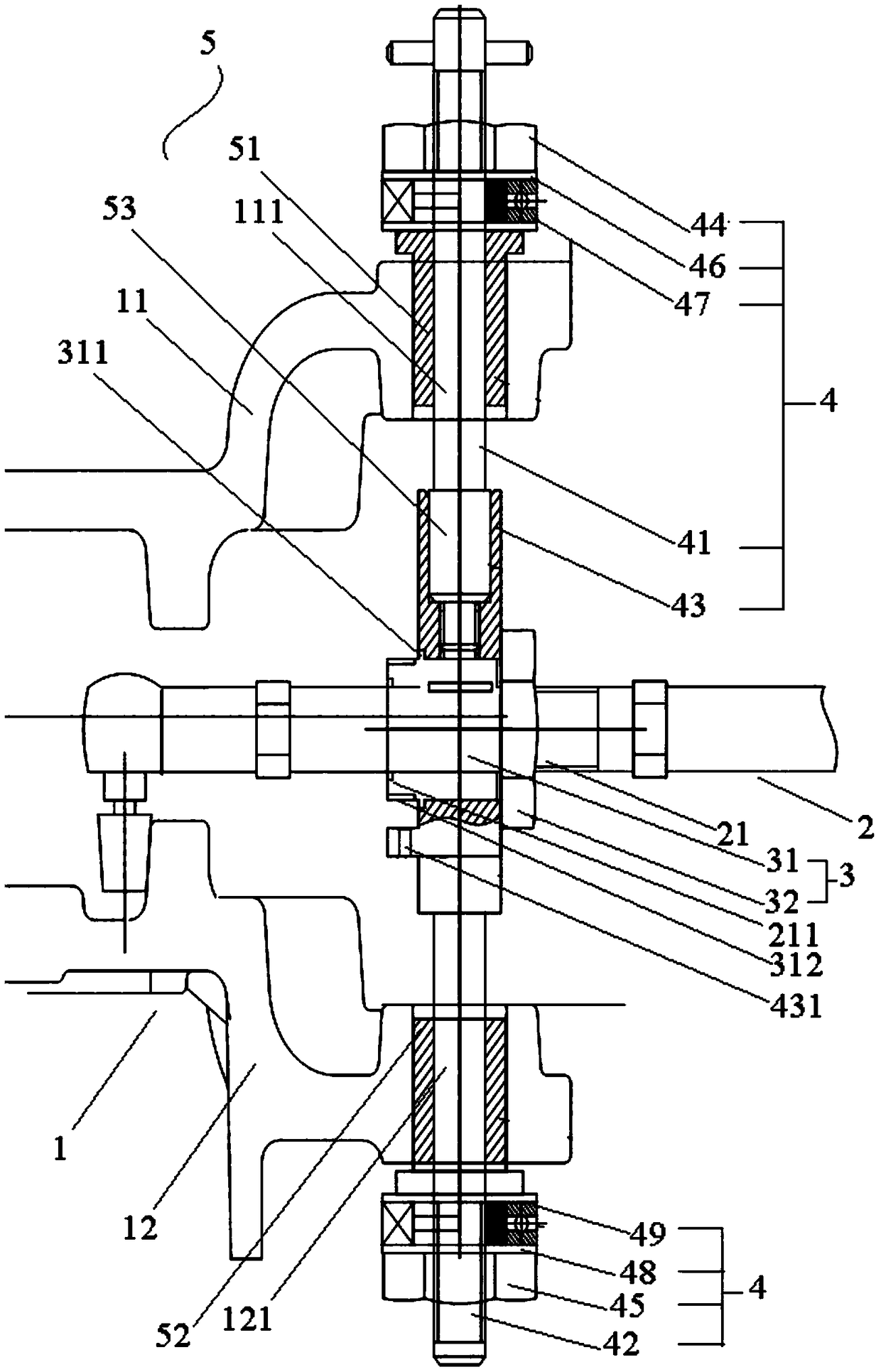
[0043] figure 1 It is a structural schematic diagram of the grinding and processing device for the coupler body...


PUM


Abstract

The invention relates to a grinding and machining device for traction tables of coupler bodies and comprises a grinding and machining device for grinding working surfaces of an upper traction table and/or a lower traction table through a cavity area between the upper traction table and/or the lower traction table of the coupler body; a radius adjusting device arranged on the grinding and machiningdevice and used for adjusting a grinding radius of the grinding and machining device; a height adjusting device which is arranged between the upper traction table and the lower traction table, installed on the radius adjusting device and used for adjusting the height of the grinding and machining device; and a circle center locating device connected to the height adjusting device and used for adjusting the height adjusting device to enable the height adjusting device to be concentric with an upper hook ear hole and a lower hook ear hole. According to the grinding and machining device for thetraction tables of the coupler bodies, the grinding and machining of the working surfaces of the upper and lower traction table is realized through positioning achieved by the upper and lower hook earholes, and the concentricity of the arc working surfaces of the upper and lower traction tables and the relative positions of the upper and lower hook ear holes is effectively improved.

Description

technical field [0001] The invention relates to a grinding tool, in particular to a grinding processing device for a traction table of a coupler body. Background technique [0002] The coupler traction table is the main stress-bearing part between the knuckle knuckle and the coupler body of the railway freight car. The working surfaces of the upper and lower traction tables are arc-shaped surfaces of concentric circles based on the 5mm lateral eccentricity of the center of the hook ear hole. During the process, the force on the upper and lower traction tables of the coupler body and the knuckle is inconsistent, resulting in eccentric load and eccentric wear, which may easily cause damage to the traction table and the hook lug, and affect driving safety. Therefore, the concentricity requirements of the upper and lower traction tables of the coupler body and knuckle must be guaranteed. . [0003] Because the arc center of the traction table working surface is inside the two ...

Claims


Application Information

Patent Timeline
Patent Type & Authority Applications(China)
IPC IPC(8): B24B19/00B24B41/00
CPCB24B19/00B24B41/00
Inventor 艾启耀王连华周增光罗万华董华锋喻泉汪珍王文峰李立群
Owner CRRC YANGTZE CO LTD
Why Eureka
Try Eureka