
In-situ finishing machine of outline grinding abrasion wheel

A dressing machine and grinding technology, which is applied to the parts of grinding machine tools, grinding/polishing equipment, abrasive surface adjustment devices, etc., can solve the problem that it cannot be used for online dressing of curved contour grinding wheels and reduces the accuracy of grinding wheel contour dressing , uncontrollable grinding wheel dressing accuracy and other problems, to avoid uneven wear, avoid the decline in the life of the roller, and improve the processing efficiency

Active Publication Date: 2019-02-22
SHANGHAI JIAO TONG UNIV
View PDF9 Cites 0 Cited by
  • Summary
  • Abstract
  • Description
  • Claims
  • Application Information

AI Technical Summary

Problems solved by technology

[0003] The existing contour grinding grinding wheel dressing mainly adopts diamond roller to trim the contour of the grinding wheel. During dressing, the diamond roller does not rotate, and the grinding wheel is trimmed through the relative movement between the grinding wheel and the cylindrical dressing roller to obtain the required contour size and shape accuracy of the grinding wheel. The dressing roller after the first use will reduce its own shape accuracy due to uneven wear, making the dressing accuracy of the grinding wheel uncontrollable and reducing the dressing accuracy of the grinding wheel profile
[0004] In order to improve the dressing performance of the grinding wheel, the Chinese invention patent application number: 201110157028.2 has announced a grinding wheel dresser, including the grinding wheel spindle and the driving spindle motor, which is mainly used for dressing the grinding wheel of the vertical grinding machine. It introduces single point dressing and double circle There are two types of camber wheel dressing, the single-point method is mainly used for auxiliary dressing, but it cannot be used for online dressing of curved profile grinding wheels

Method used


Image

  • In-situ finishing machine of outline grinding abrasion wheel
  • In-situ finishing machine of outline grinding abrasion wheel
  • In-situ finishing machine of outline grinding abrasion wheel

Examples


Embodiment Construction

[0038] The embodiments of the present invention are described in detail below. This embodiment is implemented on the premise of the technical solution of the present invention, and detailed implementation methods and specific operating procedures are provided, but the protection scope of the present invention is not limited to the following implementation example.

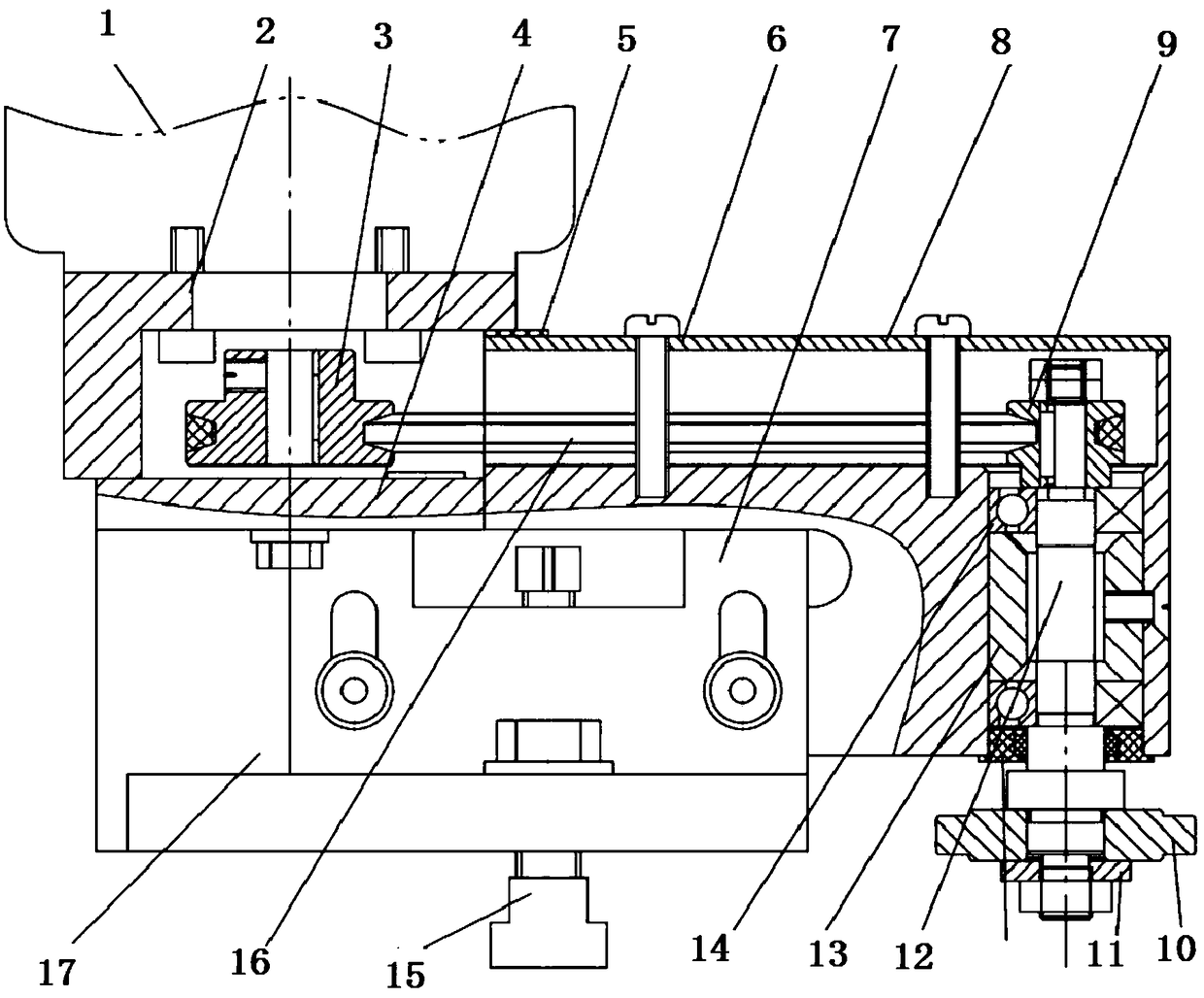
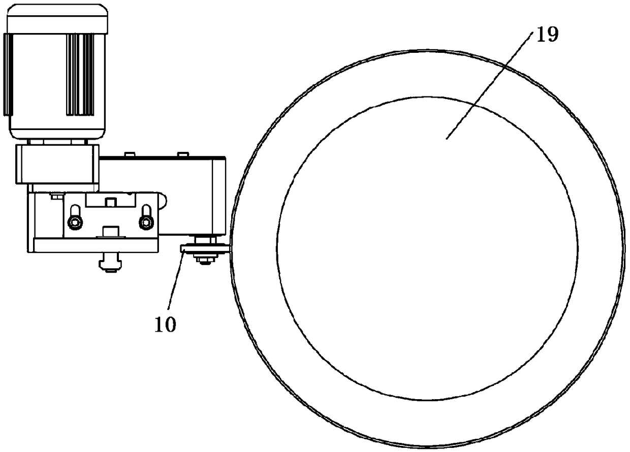
[0039] combine Figure 1-Figure 3 , describe in detail the embodiment of the contour grinding wheel in-situ dresser of the present invention, as figure 1 Shown in its cross-sectional view, such as figure 2 Shown as its front view, such as image 3 Shown is its top view, which includes: motor 1, transmission device, dressing shaft 13 and dressing roller 10; one end of the transmission device is connected to the motor 1, the other end of the transmission device is connected to the dressing shaft 13, and the dressing roller 10 is arranged on the dressing shaft 13; the transmission device is used to transmit the en...


PUM


Abstract

The invention discloses an in-situ finishing machine of an outline grinding abrasion wheel. The in-situ finishing machine comprises a motor, a transmission device, a finishing shaft and a finishing rolling wheel. One end of the transmission device is connected with the motor, and the other end of the transmission device is connected with the shaft. The finishing rolling wheel is arranged on the finishing shaft. The transmission device is used for transmitting motor energy to the finishing shaft to drive the finishing shaft to rotate, and then the finishing rolling wheel is driven to rotate. The rolling wheel axis of the finishing rolling wheel is perpendicular to the abrasion wheel axis of the to-be-ground abrasion wheel. The finishing rolling wheel is used for carrying out in-situ finishing on the to-be-ground abrasion wheel. The in-situ finishing machine of the outline grinding abrasion wheel can be used in situ, uniform wear of the finishing rolling wheel can be kept, and thereforethe finishing precision of the abrasion wheel is improved.

Description

technical field [0001] The invention relates to the technical field of contour grinding wheel processing, in particular to an in-situ dresser for contour grinding wheels. Background technique [0002] With the rapid development of the national defense industry, mold manufacturing and tool manufacturing industry, the demand for various complex and precise tools, molds and other contour curve parts is increasing. Such parts with complex contour curves not only have high hardness , the requirements for its manufacturing precision are getting higher and higher. The final processing is done by a CNC contour curve grinder using a thin double-slope arc grinding wheel to achieve contour point grinding, and the material is removed by the arc of the grinding wheel tip. The sharp arc is worn during the machining process, and its arc shape accuracy deviates from the normal value with the increase of processing time. The contour of the grinding wheel must be trimmed to ensure the grindin...

Claims


Application Information

Patent Timeline
Patent Type & Authority Applications(China)
IPC IPC(8): B24B53/06B24B53/14
CPCB24B53/06B24B53/14
Inventor 许黎明牛牧范灝赵达张哲范帆
Owner SHANGHAI JIAO TONG UNIV
Learn More