Wireless measurement and control separate injection pipe column of water injection well

A water injection well, wireless technology, used in measurement, wellbore/well components, production fluids, etc., can solve the problems of wireless transmission mode signal attenuation, affecting the life of the pipe string, short transmission distance, etc., to eliminate the risk of collision damage, The effect of improving the technical level and alleviating the lack of measurement and adjustment power

Inactive Publication Date: 2019-02-22
CHINA PETROLEUM & CHEM CORP +1
View PDF12 Cites 2 Cited by
  • Summary
  • Abstract
  • Description
  • Claims
  • Application Information

AI Technical Summary

Problems solved by technology

[0002] Layered water injection wells in oilfields are regularly tested in layers to understand the water absorption status of each separate injection layer, and at the same time adjust the water volume of the water injection layer that cannot meet the injection requirements to meet the injection requirements. Currently, the test and adjustment process of separate injection wells includes steel wire carrying test instruments After the downhole data is collected and stored, the ground is played back and read, and the water nozzle is used to adjust the water volume; the communication cable carries the measurement and adjustment integrated instrument to go down the well layer by layer to test and adjust the water volume, and the ground can directly read the data during the measurement and adjustment; The development of electronic information integration technology has also carried out technical tests such as permanent underground real-time transmission of ca

Method used


Image

  • Wireless measurement and control separate injection pipe column of water injection well

Examples


Embodiment Construction

[0016] In order to make the above and other objects, features and advantages of the present invention more comprehensible, the preferred embodiments are listed below and shown in the accompanying drawings in detail as follows.

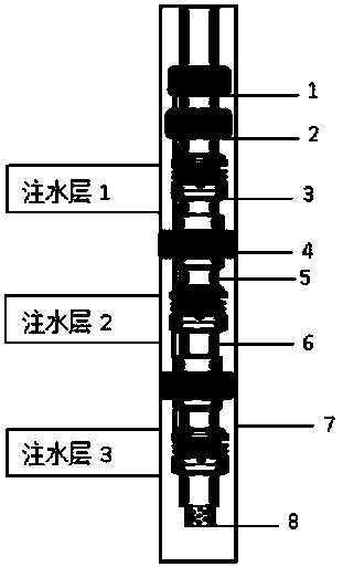
[0017] Such as figure 1 as shown, figure 1 It is a structural diagram of the wireless measurement and control dispensing string of the water injection well of the present invention. The water injection well wireless measurement and control injection string includes downhole pressure pulse transceiver device 1, downhole power supply 2, flow measurement and control device 3, cable packer 4, signal cable 5, tubing 6, casing 7, and well flushing valve 8.

[0018] The injected water enters the oil pipe 6 and flows downward until each water injection layer corresponds to the flow measurement and control device 3. The downhole pressure pulse transceiver device 1 receives the pressure signal sent by the surface pressure pulse transceiver device and converts i...


PUM


Abstract

The invention provides a wireless measurement and control separate injection pipe column of a water injection well, comprising a underground pressure pulse transmitting-receiving device, a plurality of flow measurement and control devices, a plurality of cable crossing packers and an oil pipe; a plurality of flow measurement and control devices are sealed in different water injection layers by a plurality of cable crossing packers; the underground pressure pulse transmitting-receiving device is located at the upper end of a tool section; a pressure signal received from the ground is convertedto an electrical signal and transmitted to a plurality of flow measurement and control devices so as to control the work of a plurality of flow measurement and control devices; injected water enters the oil pipe and flows downwards to the flow measurement and control devices in each water injection layer; and the water injection rate of each water injection layer can be measured by the flow measurement and control devices. The wireless measurement and control separate injection pipe column of the water injection well can meet the requirements of real-time adjustment and frequent measurement and adjustment of an injection scheme during a three-dimensional development process of an oil deposit, improve the technological level of an intelligent injection process and fill the blank of wirelesstwo-way signal transmission in the water injection field.

Description

technical field [0001] The invention relates to the technical field of oil field development, in particular to a wireless measurement and control distribution injection pipe string for water injection wells. Background technique [0002] Layered water injection wells in oilfields are regularly tested in layers to understand the water absorption status of each separate injection layer, and at the same time adjust the water volume of the water injection layer that cannot meet the injection requirements to meet the injection requirements. Currently, the test and adjustment process of separate injection wells includes steel wire carrying test instruments After the downhole data is collected and stored, the ground is played back and read, and the water nozzle is used to adjust the water volume; the communication cable carries the measurement and adjustment integrated instrument to go down the well layer by layer to test and adjust the water volume, and the ground can directly read...

Claims


Application Information

Patent Timeline
IPC IPC(8): E21B43/20E21B47/06
CPCE21B43/20E21B47/06
Inventor 王增林唐高峰马珍福崔玉海孙金峰李勇周思宏刘晋伟张凯王宏万
Owner CHINA PETROLEUM & CHEM CORP
Why Eureka
Try Eureka