Flame axial propagation velocity measurement method based on flame self-luminous property

A technology of propagation velocity and measurement method, which is applied in the direction of devices using optical methods, can solve the problems of low time resolution and insufficient precision, and achieve the effect of improving time resolution and eliminating adverse effects

Inactive Publication Date: 2019-02-22
NORTHWESTERN POLYTECHNICAL UNIV
View PDF6 Cites 6 Cited by
  • Summary
  • Abstract
  • Description
  • Claims
  • Application Information

AI Technical Summary

Problems solved by technology

[0006] The present invention aims to solve the problem of low time resolution and insufficient accuracy of measuring the flame propagation velocity in the existing detonation chamber using a pressure sensor or an ion probe, thereby providing a flame propagation velocity of a combustible gas mixture in the combustion process of the detonation chamber measurement method

Method used


Image

  • Flame axial propagation velocity measurement method based on flame self-luminous property
  • Flame axial propagation velocity measurement method based on flame self-luminous property
  • Flame axial propagation velocity measurement method based on flame self-luminous property

Examples


Embodiment Construction

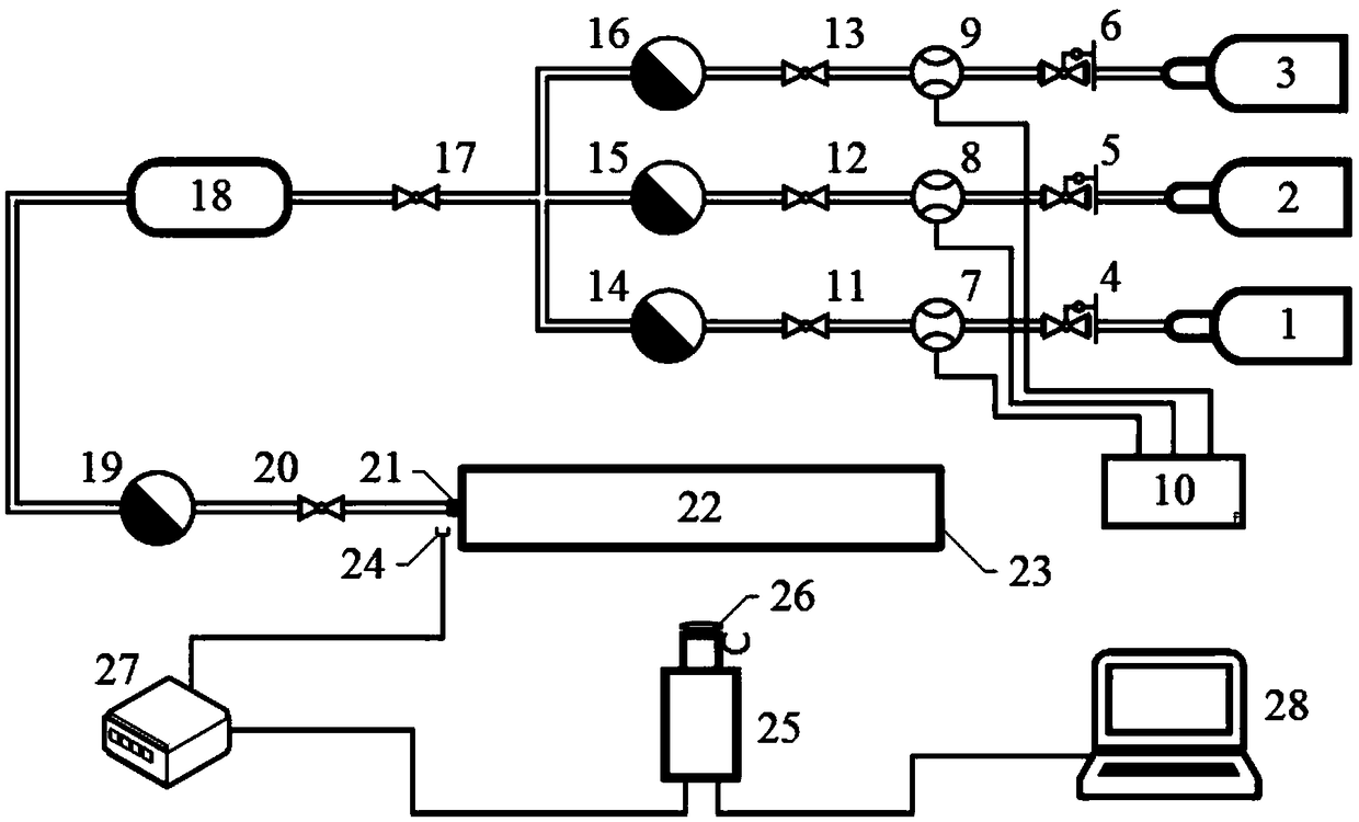
[0027] The present invention will be further described in detail below in conjunction with the accompanying drawings.

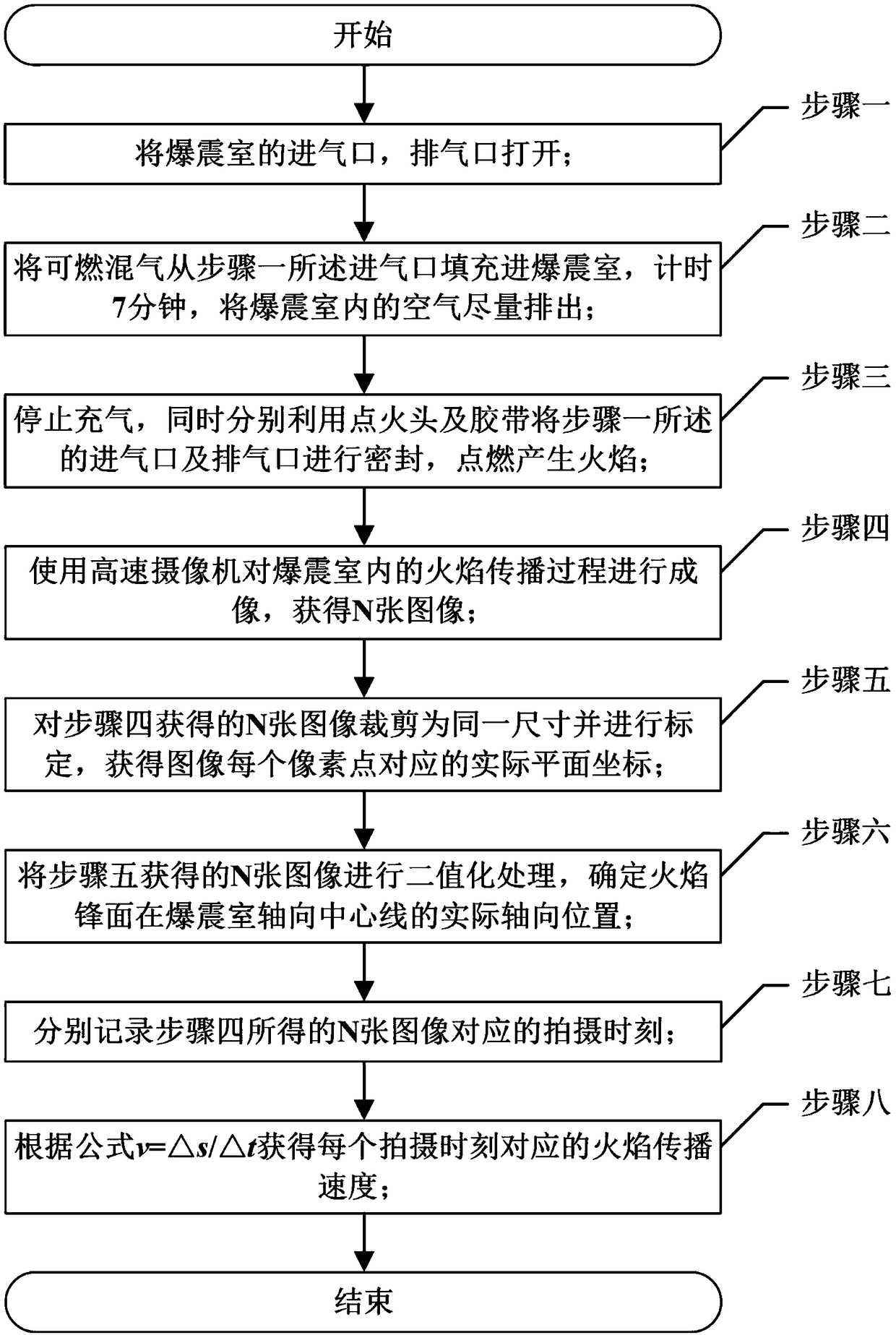
[0028] figure 1 It is a concrete step in the implementation process of the present invention, and it is realized by the following steps successively:

[0029] Step 1. Open the air inlet and exhaust port of the detonation chamber;

[0030] Step 2: Fill the combustible gas mixture into the detonation chamber from the air inlet described in step 1, time it for 7 minutes, and exhaust the air in the detonation chamber as much as possible;

[0031] Step 3. While stopping the inflation, use the ignition head and tape to seal the air inlet and exhaust port described in step 1 respectively, and ignite to generate flame;

[0032] Step 4, using a high-speed camera to image the flame propagation process in the detonation chamber to obtain N images;

[0033] Step 5. Crop the N images obtained in step 4 to the same size and calibrate them to obtain the actual plane coor...


PUM


Abstract

The invention provides a flame axial propagation velocity measurement method based on a flame self-luminous property and relates to a method for measuring the propagation velocity of a flame in a detonation chamber from a retarding state to a knocking state. The problem that the time resolution is low in detecting a flame propagation speed with a pressure sensor or an ion probe at present and theinstantaneous propagation speed of a detonation wave is difficult to obtain is solved. The method comprises a step of filling the detonation chamber with an optical window with pre-mixed combustible gas, and igniting to generate a flame to propagate downstream from the detonation chamber, a step of imaging the flame at a frame rate larger than 200 kHz by using a high-speed camera, a step of cutting, calibrating and binarizing each captured image by using MATLAB software to determine the actual axial position corresponding to a flame front at the axial centerline of the detonation chamber, anda step of calculating the propagation speed of the detonation wave according to the actual position of the flame front of each image and a shooting time. The method is suitable for the fine measurement of the speed during the study of flame propagation in the detonation chamber.

Description

technical field [0001] The invention relates to a method for measuring the speed of flame developing from slow combustion to detonation state in a detonation chamber with an optical window. Background technique [0002] Combustion is the cornerstone of the development of human society. From slash-and-burn farming to modern energy and power, they are all closely related to the phenomenon of combustion. Current research indicates that combustion waves can be divided into slow combustion waves and detonation waves. Among them, the slow combustion wave can be considered as an isobaric combustion process, while the detonation wave is based on detonation combustion, and the thermal cycle efficiency is much higher than that of the slow combustion wave based on isobaric combustion. In addition, the propagation speed of the detonation wave is on the order of kilometers per second, which is two orders of magnitude higher than that of the slow-burning wave. Therefore, under the same ...

Claims


Application Information

Patent Timeline
Patent Type & Authority Applications(China)
IPC IPC(8): G01P3/38
Inventor 范玮郑家炜赵明皓贾文杰何建男
Owner NORTHWESTERN POLYTECHNICAL UNIV
Why Eureka
Try Eureka