Method and device for precisely controlling axial fiber polishing thickness

A precise control, optical fiber technology, applied in the control of workpiece feed movement, grinding machines, manufacturing tools, etc., can solve the problems of optical fiber grinding length limitation, high technical level requirements, difficult to meet requirements, etc., to improve processing capacity and Work efficiency, achieve simultaneous grinding, and eliminate the effect of roughness

Inactive Publication Date: 2009-01-28
BEIJING JIAOTONG UNIV
View PDF4 Cites 6 Cited by
  • Summary
  • Abstract
  • Description
  • Claims
  • Application Information

AI Technical Summary

Problems solved by technology

[0002] A key process in the manufacturing process of many high-precision optical fiber devices is the grinding of the end face of the optical fiber or the axial direction of the optical fiber. When the optical fiber is polished, because it is a hard and brittle glass material, the material removal mechanism during processing is generally brittle fracture. Measures, a large number of micro-cracks or pits will inevitably be produced during the processing process, resulting in high surface roughness, which will easily cause scattering and absorption of optical signals, which is extremely unfavorable for improving the optical performance of optical fiber devices
[0003] The current optical fiber polishing technology mainly has the following three problems: First, the limitation of the length of optical fiber polishing
Although the end face grinding of optical fibers and the axial grinding of short-distance optical fibers have made great progress in recent years, the axial grinding of optical fibers with a length greater than 100mm is still a technical difficulty, and there are no related processing reports at home and abroad. , although manual grinding may increase the length of optical fiber grinding, it has high requirements for the technical level of the grinding personnel, and it takes a long time. External factors such as water vapor have a great impact on the performance of the optical fiber after grinding, and it is easy to cause a large device. loss
Second, the detection of the grinding thickness. The thickness gauge currently used is very expensive (the price of foreign products is as high as tens of thousands of dollars), and due to the characteristics of the optical fiber itself (the diameter is only 125 microns), the accuracy of the optical fiber grinding must be controlled within microns. In addition, the optical fiber is circular and transparent, so it is difficult to measure the thickness. It is difficult for the traditional thickness gauge to meet the requirements.
Third, the polishing quality of the optical fiber after grinding, foreign countries use low power C0 2 The laser light source polishes the end face of the optical fiber. Although the surface quality has been improved, the surface roughness of the end face of the optical fiber after polishing is still as high as 0.1 μm, and the optimum value of insertion loss is as high as 1.45 dB, which cannot meet the requirements of the development of optical fiber communication.

Method used


Image

  • Method and device for precisely controlling axial fiber polishing thickness
  • Method and device for precisely controlling axial fiber polishing thickness

Examples


Embodiment 1

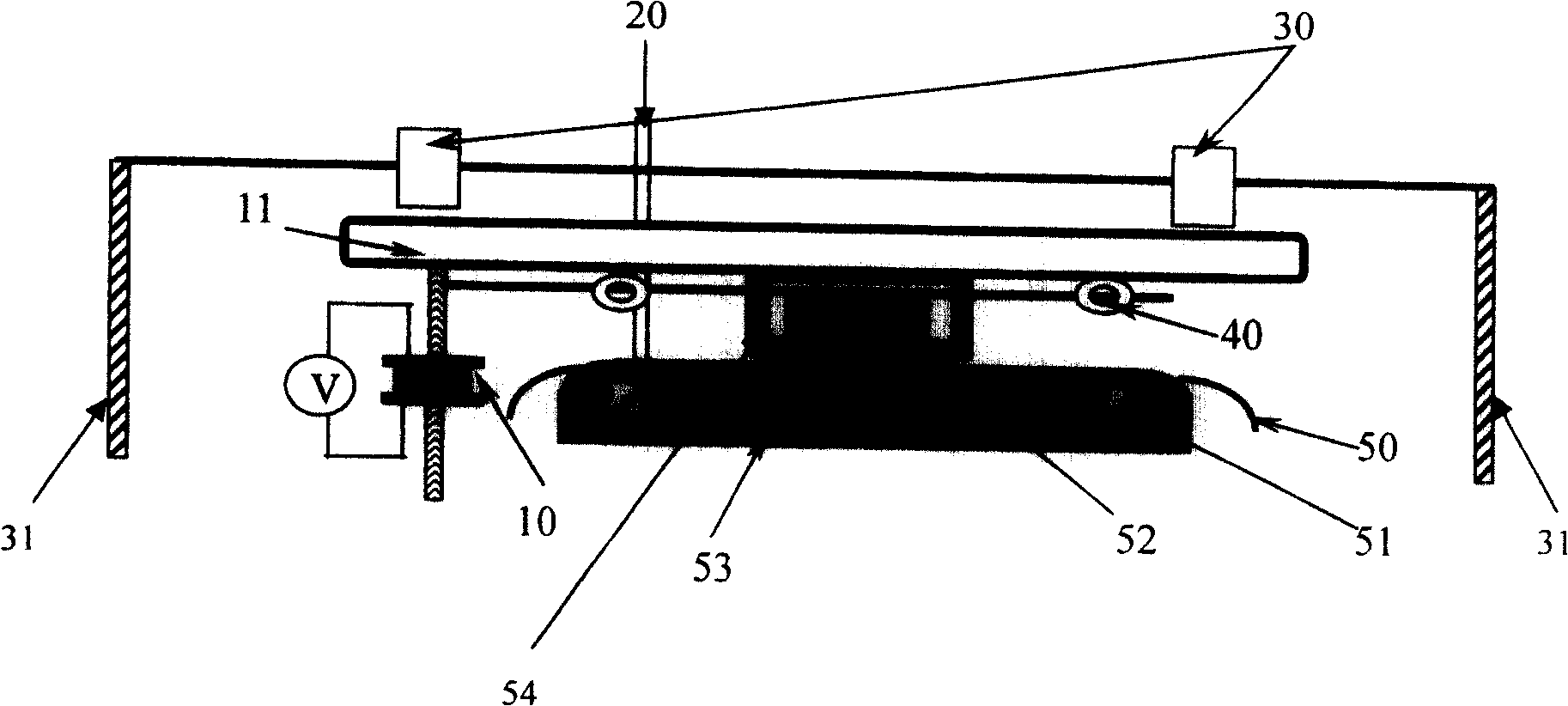
[0027] The optical fiber to be polished is placed on the glass-ceramic for placing the V-shaped grooved fiber, and the positioning reference block glass-ceramic is located at the horizontal position behind the glass-ceramic for placing the V-shaped grooved fiber, which is used to calibrate its relative height. The control motor provides the control voltage of the PZT to adjust the upper and lower positions of the V-groove optical fiber placement glass ceramics. The glass ceramics for grinding and polishing are placed on the grinding block support frame directly above the glass ceramics for placing V-shaped grooved optical fibers. The grinding block support frame is connected to the conveyor belt, and the speed of the conveyor belt is adjusted by controlling the motor to drive the grinding block. Pan in 1D at different speeds. The back-and-forth movement distance of the grinding block is determined by the positioning sensor. The electrode is placed on the slide rail just above ...

Embodiment 2

[0029] The present invention designs a novel optical fiber axial grinding device with a grinding precision as high as 0.01 μm, a grinding length greater than 100 mm, and capable of processing multiple optical fibers simultaneously ( figure 1 ).

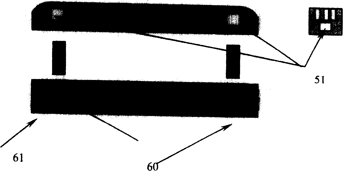
[0030] like figure 1 , 2 as shown, figure 1 , 2 Among them, 10 is the PZT grinding precision controller, 11 is the conveyor belt, whose transmission speed is controlled by the motor, 20 is the injection of grinding mud, 30 is the positioning sensor controlled by the relay, 40 is the contact point of the positioning sensor, 50 is the optical fiber to be polished, and 51 is the belt The rotatable magnet of the knob, 52 is a glass-ceramic grinding block, 53 is a glass-ceramic for V-shaped groove optical fiber placement, 60 is a clamp magnet, and 61 is a V-shaped groove for placing an optical fiber to be ground.

[0031] The control of optical fiber axial grinding accuracy is the most important parameter of optical fiber axial grindin...

Embodiment 3

[0041] Embodiment 3: The present invention can achieve grinding accuracy as high as 0.01 μm, grinding length greater than 100 mm, and simultaneous grinding of multiple optical fibers. Select multiple optical fibers to be polished with the same parameters and soak them in acetone solution for about ten minutes, then use wire strippers to remove the coating layer of optical fibers to be polished; use glass ceramics for grinding and polishing with a width greater than the total cross-sectional width of multiple optical fibers to be polished Put it on the grinding frame, then place multiple optical fibers to be polished on the glass-ceramics for placing V-shaped grooved optical fibers, and put the head and tail ends of the optical fibers to be polished into multiple parallel grooves corresponding to both ends, so that Multiple optical fibers to be polished are strictly parallel, hang them with clips to avoid movement of the optical fibers to be polished, and finally use two small m...


PUM

PropertyMeasurementUnit
surface roughnessaaaaaaaaaa
lengthaaaaaaaaaa

Abstract

The present invention is axial fiber grinding and polishing method and device with precise control on grinding and polishing thickness, controlled length and simultaneous treatment of several fibers. The fiber grinding and polishing thickness up to 0.01 micron is realized through regulating the voltage applied on the piezoelectric PZT and altering the position of the ground fiber relative to the datum block. The fiber grinding length is controlled precisely with the precise guide mechanism and locating sensor for axial grinding of fiber longer than 100 mm. One arc discharge polishing process is adopted, in which arc discharge produces high temperature to smelt the surface of the fiber under polishing to eliminate surface roughness, micro cracks and pits causing great loss. The microcrystalline glass is engraved with several V-grooves for several fibers to be set on for simultaneous processing in high work efficiency.

Description

technical field [0001] The invention relates to a method and device for precise control of the axial grinding and polishing thickness of an optical fiber with high precision (0.01 μm), large length (>100mm), and simultaneous processing of multiple optical fibers, belonging to the technical field of optical fiber communication systems, in particular to utilizing optical fiber cladding fields Changes in the technical field of making high-precision optical devices. Background technique [0002] A key process in the manufacturing process of many high-precision optical fiber devices is the grinding of the end face of the optical fiber or the axial direction of the optical fiber. When the optical fiber is polished, because it is a hard and brittle glass material, the material removal mechanism during processing is generally brittle fracture. Measures, a large number of micro-cracks or pits will inevitably be produced during the processing process, resulting in high surface roug...

Claims


Application Information

Patent Timeline
Patent Type & Authority Patents(China)
IPC IPC(8): B24B49/10B24B19/22B24B1/00B24B5/50B24B7/24
Inventor 裴丽董小伟宁提纲任文华汪滢滢
Owner BEIJING JIAOTONG UNIV
Why Eureka
Try Eureka