Thunder and lightning transient signal identification method and system based on spectral density attenuation

A transient signal and spectral density technology, applied in the direction of measuring electricity, measuring electrical variables, measuring devices, etc., can solve problems such as lack of tuning, high sampling rate requirements, and difficult identification of traveling wave heads, achieving good recognition and little impact.

Active Publication Date: 2019-02-22
ELECTRIC POWER RES INST OF STATE GRID ZHEJIANG ELECTRIC POWER COMAPNY +2
View PDF5 Cites 9 Cited by
  • Summary
  • Abstract
  • Description
  • Claims
  • Application Information

AI Technical Summary

Problems solved by technology

Scholars at home and abroad have done a lot of research on the identification of lightning transient signals on UHVDC transmission lines. Although the defects of the existing lightning transient signal id

Method used


Image

  • Thunder and lightning transient signal identification method and system based on spectral density attenuation
  • Thunder and lightning transient signal identification method and system based on spectral density attenuation
  • Thunder and lightning transient signal identification method and system based on spectral density attenuation

Examples


Embodiment 1

[0058] This embodiment proposes a lightning transient signal identification method based on spectral density attenuation, the flow chart of which is as follows Figure 11 shown.

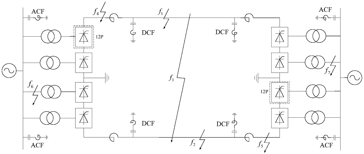
[0059] By protecting the positive and negative pole voltage data collected by the traveling wave at the installation site, the signals are collected through optical fiber communication equipment. The Karenbauer phase-mode transformation is used for electromagnetic decoupling to eliminate the influence of positive and negative pole voltage data. The per unit value of the difference between the line mode voltage and the positive axis voltage is used for transient analysis to obtain the spectral density and the energy distribution coefficient after wavelet transformation, and then identify lightning interference, lightning faults and common short-circuit faults.

[0060] The basic principle of the lightning transient signal identification method based on spectral density attenuation provided by the pre...

Embodiment 2

[0095] This embodiment provides a lightning transient signal identification system based on spectral density attenuation, including:

[0096] Data acquisition and processing module: extract the collected data at all levels after the arrival of the traveling wave, and perform voltage component phase-mode transformation and standard unit conversion;

[0097] Wavelet singular entropy calculation module: perform wavelet transformation on transient signals and calculate wavelet singular entropy;

[0098] Transient signal identification module: judge the ratio of spectral density, and identify fault signals, shielding interference signals and counter-attack interference signals;

[0099] Fault signal judgment module: judge the energy distribution coefficient of wave recording data, and identify ordinary short-circuit fault signals and lightning fault signals.


PUM


Abstract

The invention discloses a thunder and lightning transient signal identification method and system based on spectral density attenuation. In an existing thunder and lightning transient signal identification scheme, a traveling wave head is difficult to identify, a sampling rate requirement is high, and setting lacks a theoretical basis and so on. The method of the invention is characterized by extracting the transient signal of a direct current power transmission system and carrying out wavelet transform, calculating a wavelet singular entropy, determining the ratio of a spectrum density, and identifying a fault signal, a lightning shielding failure interference signal, and a counter interference signal; and determining according to a recorded data energy distribution coefficient, and identifying a common short circuit fault signal and a lightning fault signal. In the invention, a thunder and lightning transient signal can be well identified, and the method and the system are less affected by factors such as a fault distance, a transition resistance and the like.

Description

technical field [0001] The invention belongs to the technical field of power system fault identification, and relates to a lightning transient signal identification method and system based on spectrum density attenuation. Background technique [0002] UHVDC power transmission projects are usually long-distance power transmission, with long transmission lines and harsh geographical environments. Therefore, the transmission lines have a high probability of being struck by lightning and failure. Statistics show that the DC transmission line has the highest probability of failure in UHVDC transmission projects, but the correct action rate of DC line protection is only 50%. At the same time, a large part of the faulty operation of existing line protection devices is due to the impact of lightning interference, etc. . The fault restart function can be used to restore the normal operation of the line after the DC line fails, without blocking the DC system. Therefore, researching ...

Claims


Application Information

Patent Timeline
IPC IPC(8): G01R31/08
CPCG01R31/085G01R31/088
Inventor 胡列翔赵光静王增平韩志军张亚刚马静裘愉涛陆承宇王松戚宣威吴佳毅孟繁岐梁嘉娣汪冬辉孙文文阮黎翔丁峰陈明
Owner ELECTRIC POWER RES INST OF STATE GRID ZHEJIANG ELECTRIC POWER COMAPNY
Why Eureka
Try Eureka