Phased array radar decoupling method

A technology of phased array radar and phased array antenna, which is applied in the field of radar decoupling, and can solve problems such as beam instability and inability to realize phased array antenna movement

Active Publication Date: 2019-02-22
BEIJING INST OF REMOTE SENSING EQUIP
View PDF4 Cites 6 Cited by
  • Summary
  • Abstract
  • Description
  • Claims
  • Application Information

AI Technical Summary

Problems solved by technology

[0003]Aiming at the above technical problems, the present invention provides a phased array radar decoupling method, which solves the proble...

Method used


Image

  • Phased array radar decoupling method
  • Phased array radar decoupling method
  • Phased array radar decoupling method

Examples


Embodiment approach 1

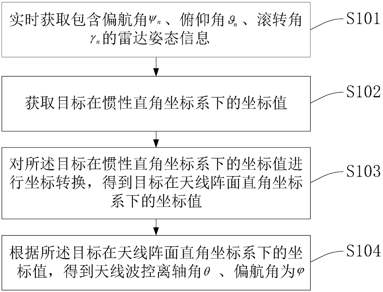
[0057] A kind of phased array radar decoupling method of the present invention, such as figure 1 shown, including steps:

[0058] S101. Real-time acquisition including yaw angle ψ n ,Pitch angle roll angle gamma n radar attitude information;

[0059] The radar attitude information includes the yaw angle, pitch angle, and roll angle of the radar. The radar attitude information can be obtained by inertial navigation or other measurement equipment. There is no special limitation here. The real-time information of the radar attitude information The performance is determined by the communication data rate.

[0060] Units of the yaw angle, pitch angle, and roll angle may be degrees or radians, which are not particularly limited here.

[0061] S102. Obtain the coordinate value of the target in the inertial Cartesian coordinate system;

[0062] S103. Perform coordinate transformation on the coordinate values ​​of the target in the inertial Cartesian coordinate system, and obtai...

Embodiment approach 2

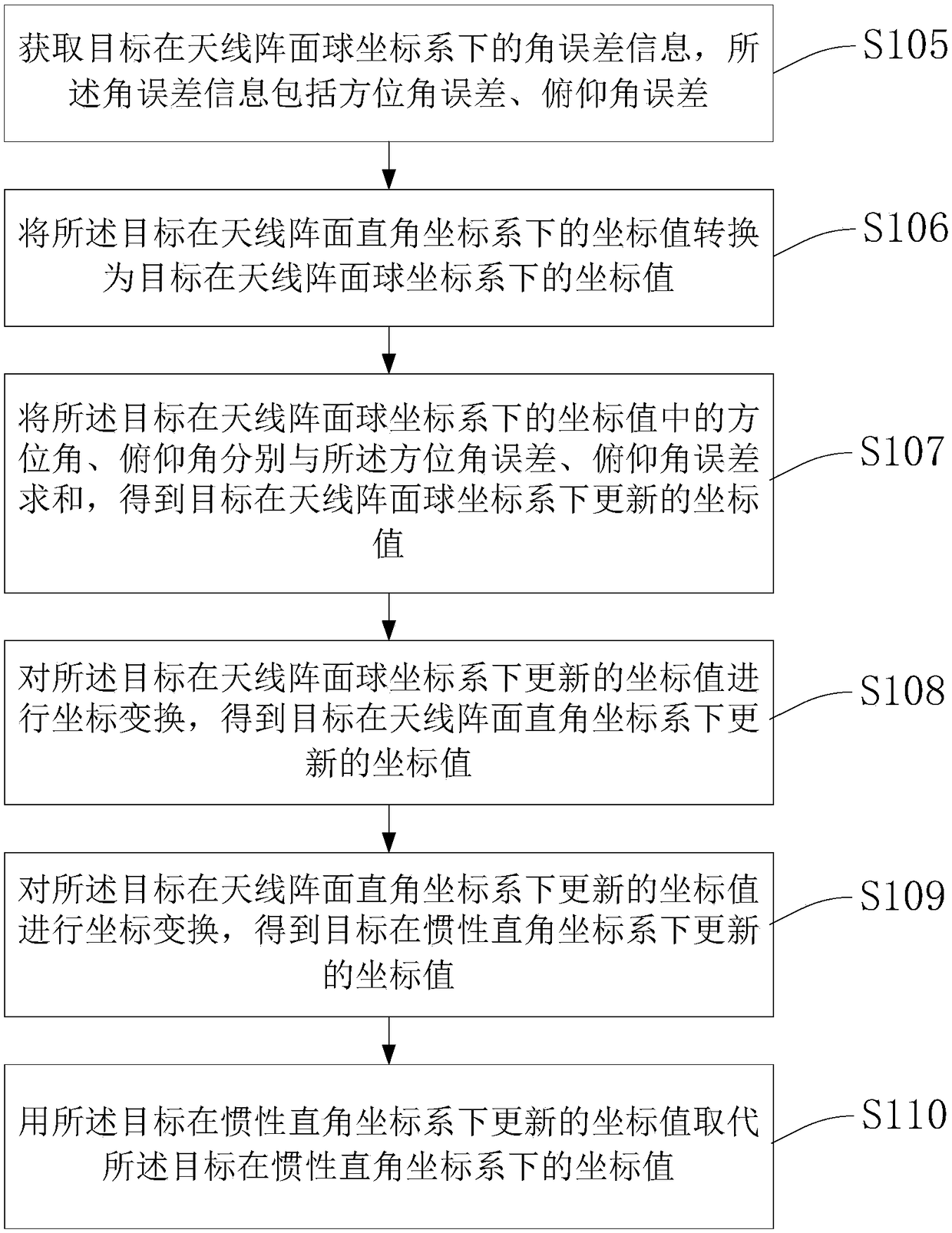
[0071] The present invention also provides a phased array radar decoupling method including angle error information, wherein steps S101 to S104 are the same as those in Embodiment 1, and further include steps:

[0072] S105. Obtain angular error information of the target in the spherical coordinate system of the antenna array, where the angular error information includes an azimuth error and an elevation angle error; the angular error information is obtained by radar measurement.

[0073] S106. Convert the coordinate values ​​of the target in the rectangular coordinate system of the antenna front to the coordinate values ​​of the target in the spherical coordinate system of the antenna front.

[0074] S107. Summing the azimuth and elevation angles of the target in the coordinate values ​​of the target in the antenna array spherical coordinate system and the azimuth angle error and the pitch angle error, respectively, to obtain the update value of the target in the antenna array...

Embodiment approach 3

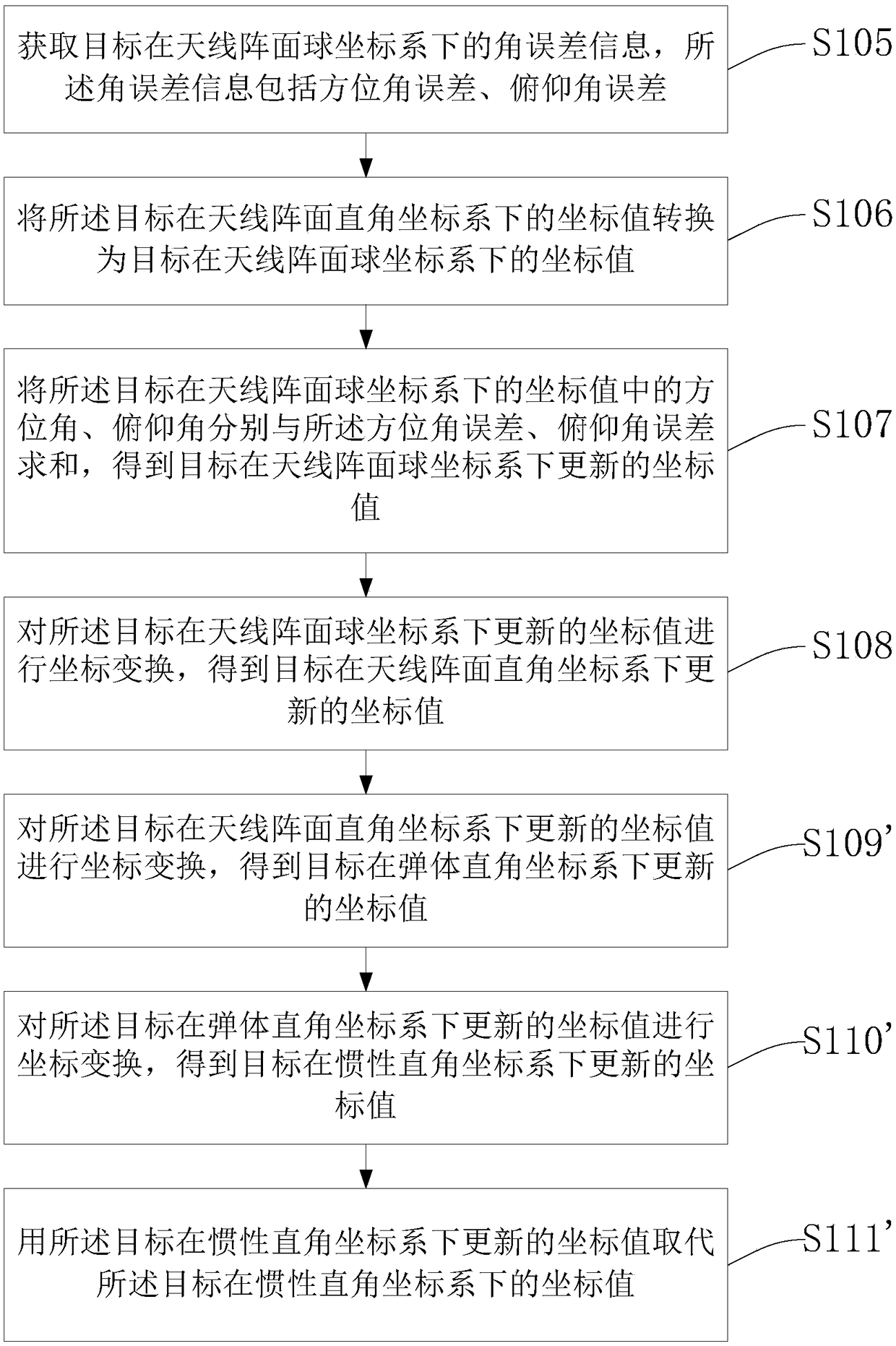
[0081] The present invention also provides a phased array radar decoupling method including coordinate update, the flow chart is as follows image 3 As shown, steps S101 to S104 are the same as those in Embodiment 1,

[0082] S105. Obtain angular error information of the target in the spherical coordinate system of the antenna array, where the angular error information includes an azimuth error and an elevation angle error; the angular error information is obtained by radar measurement.

[0083] S106. Convert the coordinate values ​​of the target in the rectangular coordinate system of the antenna front to the coordinate values ​​of the target in the spherical coordinate system of the antenna front.

[0084] S107. Summing the azimuth and elevation angles of the target in the coordinate values ​​of the target in the antenna array spherical coordinate system and the azimuth angle error and the pitch angle error, respectively, to obtain the update value of the target in the anten...


PUM


Abstract

The invention discloses a phased array radar decoupling method. The method comprises the following steps: acquiring radar attitude information including a yaw angle psi n, an elevation angle and a roll angle gamma n in real time; acquiring a coordinate value of a target in an inertial rectangular coordinate system; carrying out coordinate transformation on the coordinate value of the target in theinertial rectangular coordinate system to obtain a coordinate value of the target in a rectangular coordinate system of an antenna array surface; and acquiring an antenna wave-control off-axis angletheta and a yaw angle phi according to the coordinate value of the target in the rectangular coordinate system of the antenna array surface. On the basis of the characteristics of beam pointing controllability of the phased array antenna, the external interference information is transformed in the phased-array antenna array coordinate system for open loop compensation; and the beam pointing angelof the phased array antenna is updated by using the compensated beam pointing angle.

Description

technical field [0001] The invention relates to a radar decoupling method, in particular to a phased array radar decoupling method. Background technique [0002] The target measurement value obtained by measuring the radar target is carried out in the antenna coordinate system. Since the antenna coordinate system is a moving coordinate system, the position of the beam radiated by the antenna will change with the movement of the antenna coordinate system. The radar radiated by the antenna The change of the beam position relative to the change of the target position is a fast-changing information, which causes the antenna beam to fail to align with the target and cause the target to be lost. Therefore, it is necessary to decouple the interference caused by the movement of the antenna coordinate system. The research on the existing decoupling algorithm is mainly aimed at the radar system combined with the monopulse antenna and the servo structure. The servo uses the angle error...

Claims


Application Information

Patent Timeline
IPC IPC(8): G01S7/02
CPCG01S7/023
Inventor 刘琳常立超张永杰马路
Owner BEIJING INST OF REMOTE SENSING EQUIP
Why Eureka
Try Eureka