
A miniature complementary lighting system for an under-screen fingerprint identification module

A fingerprint recognition module and lighting system technology, applied in the field of fingerprint recognition, can solve the problems of mobile phone display black spots, lighting, power consumption, etc.

Pending Publication Date: 2019-02-22
MIKOLTA OPTICAL TECH CO
View PDF1 Cites 21 Cited by
  • Summary
  • Abstract
  • Description
  • Claims
  • Application Information

AI Technical Summary

Problems solved by technology

OLED screens consume a lot of power when displaying images with a white background (such as documents or websites)
Another disadvantage is the burn-in problem: due to the difference in the display of each pixel on the screen, the aging speed of each location is different
Then, since the opening position of the light guide plate cannot illuminate the LCD display directly above, an obvious black spot will appear on the display of the mobile phone.
[0005] For this reason, how to solve the black spots on the display screen caused by the opening of the light guide plate has become an urgent problem to be solved in the current fingerprint recognition technology under the screen.

Method used


Image

  • A miniature complementary lighting system for an under-screen fingerprint identification module
  • A miniature complementary lighting system for an under-screen fingerprint identification module
  • A miniature complementary lighting system for an under-screen fingerprint identification module

Examples


specific Embodiment approach 1

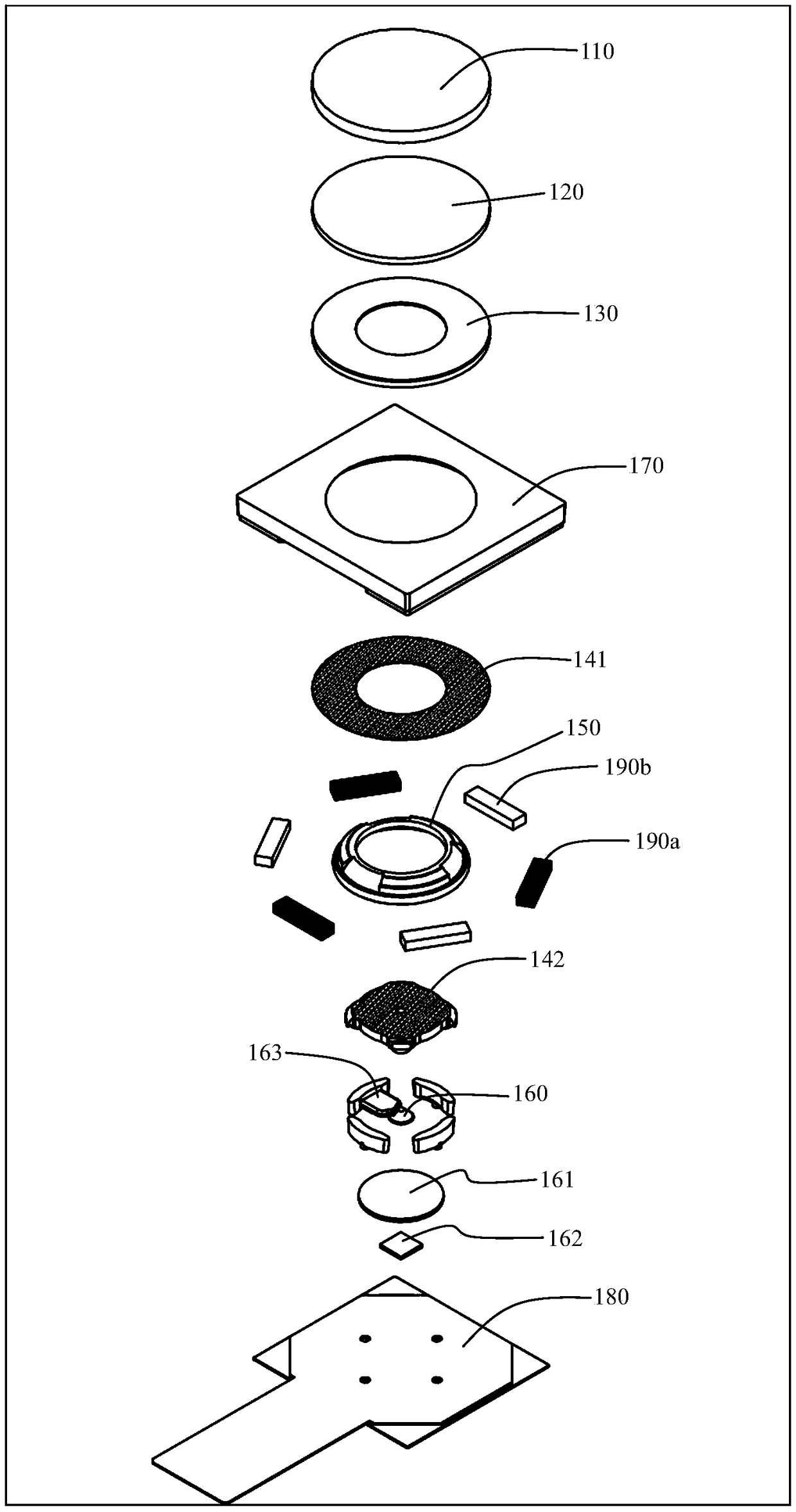
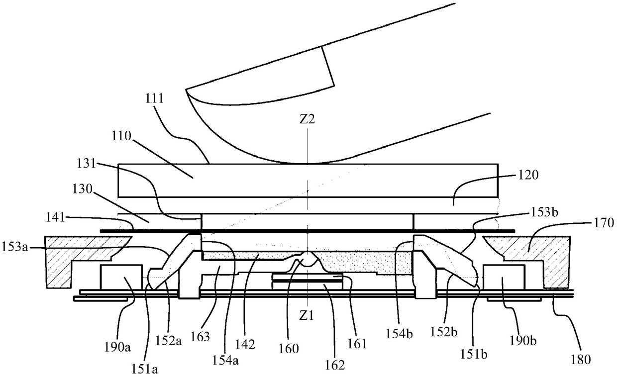
[0146] The present invention relates to a miniature supplementary lighting system for an under-screen fingerprint identification module. The supplementary backlighting system described in Embodiment 1 adopts two lighting modes of infrared and white LED light sources respectively. Its three infrared LEDs adopt the oblique lighting method of large-angle blind field of view, and directly illuminate the fingerprint skin on the surface of the glass cover of the mobile phone touch screen from the side at a large oblique angle. The other three white LEDs are used to evenly supplement the lighting through the mixed light cavity formed by the upper and lower reflective surfaces. The position is basically the same as the light distribution.

[0147] The miniature supplementary backlight lighting system is ring-shaped, that is, the light mixing cavity formed by the upper and lower reflective surfaces, the free-form surface concentrating and turning prism for light guiding, and the arrang...

specific Embodiment approach 2

[0167] A miniature supplementary light lighting system for an under-screen fingerprint recognition module related to the present invention adopts two kinds of lighting modes of infrared light and white light LED light source respectively. Its three infrared LEDs adopt the oblique lighting method of large-angle blind field of view, and directly illuminate the fingerprint skin on the surface of the glass cover of the mobile phone touch screen from the side at a large oblique angle. The other three white LEDs pass through the light mixing cavity formed by the upper and lower reflectors to evenly supplement the illumination of the black spots on the mobile phone display due to the opening of the light guide plate of the mobile phone backlight module. The position is basically the same as the light distribution.

[0168] In the miniature supplementary backlighting system, in the light mixing cavity, there is a small through hole in the middle of the reflector below it, which is two...

specific Embodiment approach 3

[0186] The present invention relates to a miniature supplementary light lighting system for fingerprint recognition modules under the screen, the supplementary backlight lighting system, the light mixing cavity between the two reflectors, the middle area can be set as The filling structure, that is, adding a lens to make it fit with the light guide plate of the mobile phone LCD screen without gaps, avoiding the double image phenomenon of the aperture diaphragm in the middle of the lower reflective sheet when observing from the outside to the inside; and the imaging lens, The part of the outer ring used for assembly can be made into light-absorbing black by means of two-color injection molding, as described in Embodiment 3 of this embodiment.

[0187] The working method of the miniature supplementary backlight lighting system and imaging system described in its specific embodiment 3 is as follows: Figure 18 shown. The dark field illumination method for the infrared light on t...


PUM

PropertyMeasurementUnit
angle of incidenceaaaaaaaaaa
diameteraaaaaaaaaa
diameteraaaaaaaaaa

Abstract

The invention provides a miniature complementary lighting system for an under-screen fingerprint identification module. The miniature complementary lighting system is located between a light guide plate of a liquid crystal screen and an imaging module for fingerprint identification, and is used for supplementing the illumination of the liquid crystal screen and eliminating black spots on the liquid crystal screen caused by holes in the light guide plate. The miniature supplemental lighting system comprises more than two LED light sources symmetrically distributed with the imaging module as thecenter and a folded optical path assembly composed of more than two reflecting surfaces. The light emitted from the LED light source is reflected and mixed for many times by means of the folded lightpath assembly, and the mixed light uniformly illuminates the liquid crystal screen above. As that light guide plate assembly is open and the light guide lines are partially cancel, the black spots onthe mobile phone display screen can be eliminated, the light distribution is basically the same as that of other positions of the liquid crystal screen, and the lower skin of the fingerprint can be illuminate.

Description

technical field [0001] The invention relates to fingerprint identification technology, in particular to a miniature supplementary light lighting system (that is, a miniature supplementary backlight lighting system) used for an under-screen fingerprint identification module. Background technique [0002] Recently, due to the wide application of full-screen mobile phones, more and more mobile phones have adopted the fingerprint recognition module under the screen. Most of the currently popular off-screen fingerprint recognition modules on the market are capacitive fingerprint sensor components, which use silicon wafer microarrays and conductive subcutaneous electrolytes to form an electric field. There are different changes in the difference, whereby accurate fingerprint determination can be achieved. However, since the surface of the sensor is made of silicon material, it is easily damaged, resulting in a reduced service life. And the fingerprint image is formed by the groo...

Claims


Application Information

Patent Timeline
Patent Type & Authority Applications(China)
IPC IPC(8): G06K9/00G02F1/13357
CPCG02F1/133603G02F1/133605G02F1/133606G02F1/133611G02F1/133607G06V40/1324
Inventor 郎欢标
Owner MIKOLTA OPTICAL TECH CO
Learn More