
Reheating energy-saving tea leaf roller fixation machine

A technology of drum-fixing machine and tea, applied in the direction of tea treatment before extraction, can solve the problems of insufficient utilization of heat, affecting the quality of tea leaves, black spots of tea leaves, etc., to reduce heat loss, discharge water vapor in time, and prevent The effect of black dots

Pending Publication Date: 2019-03-01
NANNING CHUANGYU TEA MACHINERY
View PDF0 Cites 0 Cited by
  • Summary
  • Abstract
  • Description
  • Claims
  • Application Information

AI Technical Summary

Problems solved by technology

[0004] When the metal drum is heated, the heat only comes from the combustion chamber below the drum. Because the firepower cannot be evenly distributed throughout the entire combustion chamber, the temperature of the drum directly above the furnace bridge is the highest. At the same time, the fresh tea leaves are heated to produce a large amount of steam, which inevitably leads to Black spots, stuffy yellow and other phenomena will seriously affect the quality of tea
[0005] The heat generated by the combustion of fuel in the combustion chamber of the lower furnace body is directly discharged or drawn out from the smoke exhaust port on the upper furnace body along with the flue gas. A large amount of heat is not fully utilized, resulting in low thermal efficiency and high energy consumption.

Method used


Image

  • Reheating energy-saving tea leaf roller fixation machine
  • Reheating energy-saving tea leaf roller fixation machine
  • Reheating energy-saving tea leaf roller fixation machine

Examples


Embodiment Construction

[0020] The technical solutions of the present invention will be further described in detail below in conjunction with the drawings and embodiments.

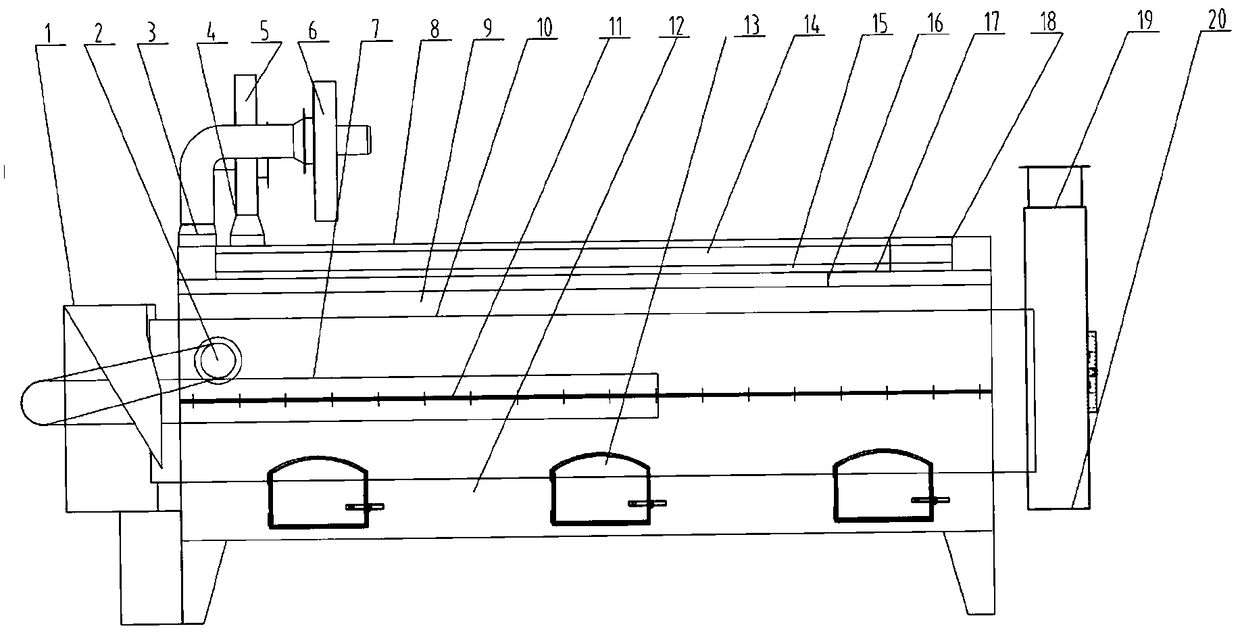
[0021] Such as figure 1 , The embodiment of the present invention provides a reheating energy-saving tea drum curing machine, comprising an upper furnace body 9, a lower furnace body 12, a drum 10 and a shell 8, wherein the upper furnace body 9 and the lower furnace body 12 are connected by a flange 11. A cylindrical furnace is formed. The drum 10 is located inside the cylindrical furnace and is supported by rollers. It can roll in the furnace under the drive of driving force. The outer shell 8 is located on the upper furnace body 9. Play the role of dustproof and prevent operators from being burned.

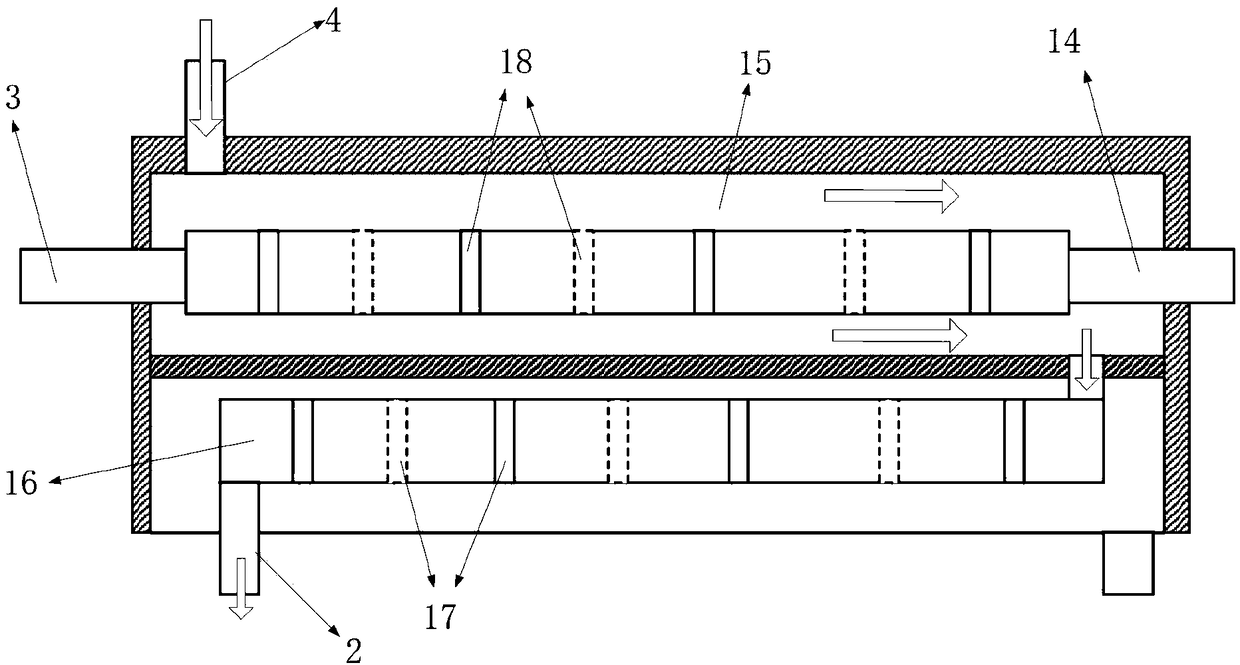
[0022] Such as figure 2 , The upper furnace body 9 includes two upper and lower layers, the upper layer is a smoke pipe interlayer 15, the smoke pipe interlayer 15, and the lower layer is provided with an air duct 16. The flue pipe 14...


PUM


Abstract

The invention relates to an reheating energy-saving tea leaf roller fixation machine. The reheating energy-saving tea leaf roller fixation machine comprises an upper furnace body, a lower furnace body, a roller and a housing, wherein the upper furnace body and the lower furnace body form a cylindrical furnace chamber; the roller is located in the cylindrical furnace chamber; a wind inlet, a smokeexhaust opening and a thermal wind outlet are formed in the housing; the wind inlet is connected with the left end of a flue pipe interlayer; combustion chambers are arranged in the lower furnace body; the upper layer of the upper furnace body is the flue pipe interlayer; a flue pipe which penetrates through the flue pipe interlayer is arranged in the flue pipe interlayer; a wind channel is arranged in the lower layer of the upper furnace body; two ends of the wind channel are respectively connected with the flue pipe interlayer and the thermal wind outlet; two ends of the flue pipe are respectively connected with the combustion chambers and the smoke exhaust opening; a thermal wind pipe is arranged at the left end of the roller; and two ends of the thermal wind pipe are respectively connected with the thermal wind outlet and the center of the roller. Under the effect of high-temperature thermal wind produced in an upper furnace body, fresh tea leaves in the roller are more uniform toheat, the steam is more timely to drain, and generation of phenomena of black points, heaping for yellowing and the like is effectively avoided.

Description

Technical field [0001] The invention relates to the technical field of tea curing, in particular to a reheating energy-saving tea drum curing machine. Background technique [0002] Roller continuous burnishing machine is generally composed of upper furnace body, lower furnace body, burnishing roller and transmission mechanism. [0003] When the drum curing machine is working, the metal drum rotates at a constant speed and is heated by the fuel in the combustion chamber of the lower furnace body; the fresh tea leaves make a projectile motion in the drum and move forward under the action of the guide vane. The fresh tea leaves absorb the heat conducted by the heat radiation of the cylinder, and the temperature rises rapidly, and the enzyme activity is destroyed in a short time, thereby achieving the effect of killing. [0004] When the metal drum is heated, the heat only comes from the combustion chamber below the drum. Because the fire point cannot be evenly distributed throughout th...

Claims


Application Information

Patent Timeline
Patent Type & Authority Applications(China)
IPC IPC(8): A23F3/06
CPCA23F3/06
Inventor 高生福廖勤明刘晓东庞月兰郭春雨卿燕高生春杨明帮潘学伟廖少康刘赛堂董朝文
Owner NANNING CHUANGYU TEA MACHINERY
Learn More