Internal spinning device

An internal spinning and equipment technology, applied in the field of internal spinning forming, can solve the problems of too long rotor arm, large friction force, and inability to demold the workpiece, and achieve the effect of satisfying precise control and improving rigidity

Active Publication Date: 2019-02-26
AEROSPACE INST OF ADVANCED MATERIALS & PROCESSING TECH
View PDF6 Cites 4 Cited by
  • Summary
  • Abstract
  • Description
  • Claims
  • Application Information

AI Technical Summary

Problems solved by technology

However, the mold length of the internal spinning technology is required to be longer than the product length, which is difficult to manufacture, low in assembly accuracy, and high in production costs. Most importantly, this process can only produce products with a length of less than 1m. If the product is too long, the workpiece If the contact area between the outer surface and the mold is too large, the friction force is large, and the workpiece will not be released from the mold, so it cannot be applied to the production of large-diameter, high-precision long cylindrical parts required for the development of the national defense industry.
[0004] Existing internal spinning equipment such as Image 6 As shown, (including spinning machine body 01, mandrel 02, rotary wheel 03, workpiece 04, balance wheel mechanism 05, screw 06, binder ring 07, rotary wheel arm 08, and lateral carriage 09), use Lateral L-shaped cantilever type single-rotary wheel internal spinning mechanism, the shaft and radial feed of the rotary wheel 03 are driven by the lateral carriage 09 to drive the L-shaped rotary wheel arm 08 fixed to it, and the overall axis is driven by the motor. , Radial movement is realized, the spinning wheel arm is too long, the rigidity of single wheel spinning is extremely low, it is impossible to realize automatic centering spinning, and the spinning force is small, it is impossible to carry out spinning processing of thick-walled difficult-to-form materials, and cannot meet high-precision Product processing

Method used


Image

  • Internal spinning device
  • Internal spinning device
  • Internal spinning device

Examples


Embodiment Construction

[0026] The present invention will be described in detail below in conjunction with specific examples and accompanying drawings.

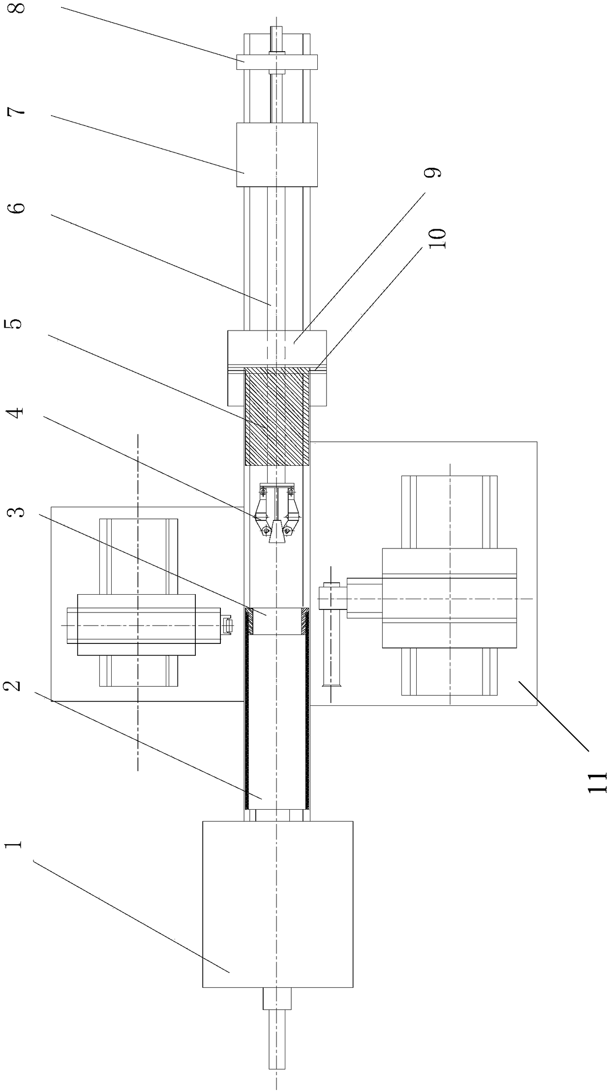
[0027] Spinning equipment such as figure 1 As shown, it includes the spindle box 1, the mold transmission cylinder 2, the rotary wheel mechanism, the traction mechanism 9, the binder ring 10 and the CNC machine bed 11, the mold transmission cylinder 2 is installed on the CNC machine tool spindle, and the mold 3 is installed on the mold transmission cylinder 2. The front end of the inner cavity, the wheel mechanism and the traction mechanism 9 are installed on the bed 11 of the CNC machine tool.

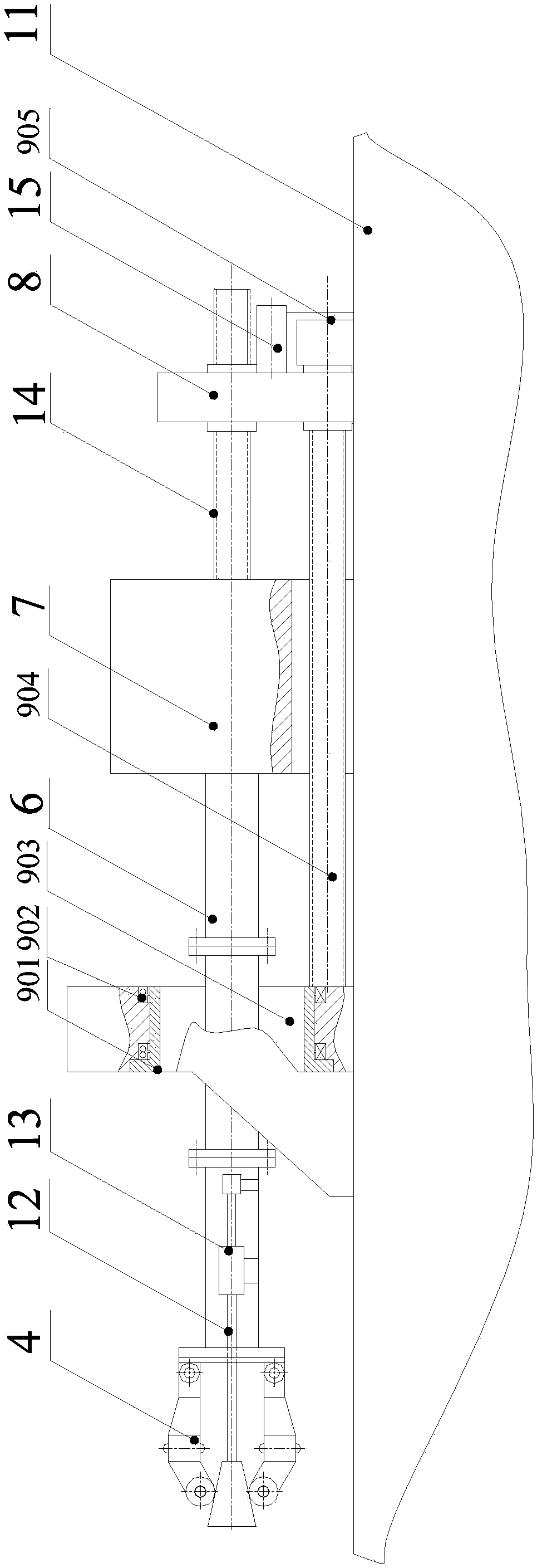
[0028] traction mechanism 9 such as image 3 As shown, it includes a traction mechanism rotor 901, a traction mechanism rotor bearing 902, a traction mechanism seat 903, a traction mechanism axial feed screw 904 and a traction mechanism axial feed drive motor 905. The traction mechanism rotor 901 passes through the traction mechanism The rotating body be...


PUM


Abstract

The invention provides an internal spinning device, which comprises a spindle box, a die transmission cylinder, a rotating wheel mechanism, a traction mechanism, a material pressing ring and a numerical control machine tool body, wherein the rotating wheel mechanism comprises a rotating wheel head mechanism, a rotating wheel radial feeding structure, a rotating wheel arm, a rotating arm seat and an axial feeding structure. According to the invention, two kinds of axial motions can be achieved on the same axis, a motion space is provided for an internal spinning and tension spinning composite process by adopting a traction mechanism, the internal spinning traction mechanism and the spinning wheel mechanism are coaxial and move independently from each other, and a guarantee is provided for achieving the composite spinning process.

Description

technical field [0001] The invention relates to an internal spinning equipment, which belongs to the technical field of internal spinning. Background technique [0002] External spinning is a traditional spinning process technology. The external spinning technology can produce long-length cylindrical rotary parts with external reinforcing ribs. It has high efficiency, can be heated for spinning, and can process curved generatrix shapes. And tapered parts and other characteristics. However, the length of the external spinning die is required to be longer than the length of the product, which is difficult to manufacture, low in assembly accuracy, and high in production costs. Most importantly, products with inner circumferential ribs formed by the external powerful spinning process must be split Molds must be disassembled and reassembled every time a product is produced. The production efficiency is extremely low and it is not suitable for mass production. It has been unable ...

Claims


Application Information

Patent Timeline
Patent Type & Authority Applications(China)
IPC IPC(8): B21D22/14
CPCB21D22/14
Inventor 马世成王东坡张月倩张晨汪宇羿赵文龙
Owner AEROSPACE INST OF ADVANCED MATERIALS & PROCESSING TECH
Why Eureka
Try Eureka