Spray nozzle for catalytic cracking and application

A catalytic cracking and nozzle technology, which is applied in the direction of catalytic cracking, cracking, injection devices, etc., can solve the problem of being unable to simulate the ejection, contact and reaction of various heavy diesel oils, and achieve the effects of promoting high-efficiency conversion, simple structure, and convenient use

Active Publication Date: 2019-02-26
PETROCHINA CO LTD
View PDF9 Cites 0 Cited by
  • Summary
  • Abstract
  • Description
  • Claims
  • Application Information

AI Technical Summary

Problems solved by technology

When the catalytic cracking riser test device is used to simulate the blending of heavy diesel oil in industrial catalytic cracking units, because the existing feed nozzle can only spray out one kind of catalytic cracking raw material, it is impossible to simulate the contact and reaction of various heavy diesel oils with the catalyst

Method used


Image

  • Spray nozzle for catalytic cracking and application
  • Spray nozzle for catalytic cracking and application
  • Spray nozzle for catalytic cracking and application

Examples


Embodiment 1

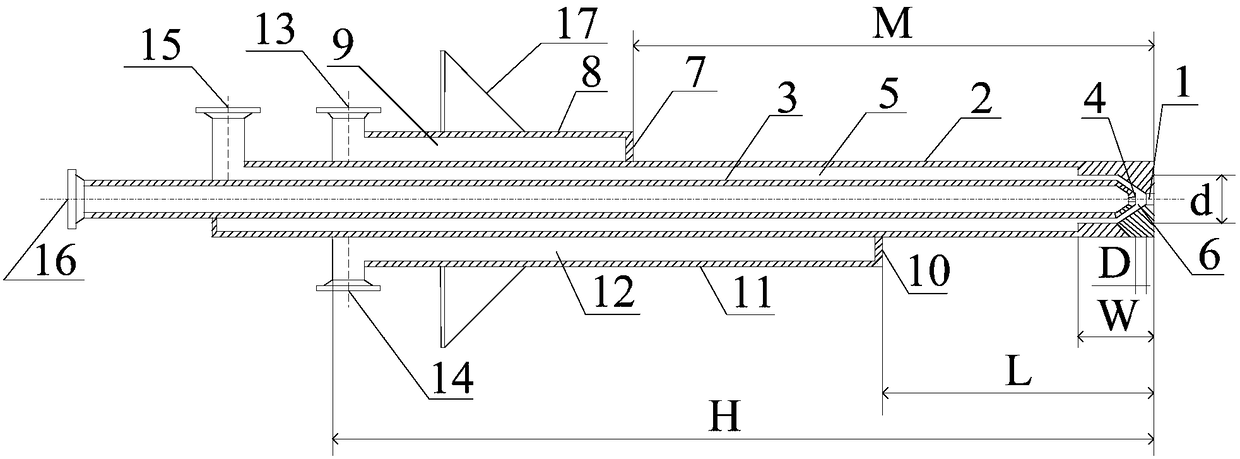
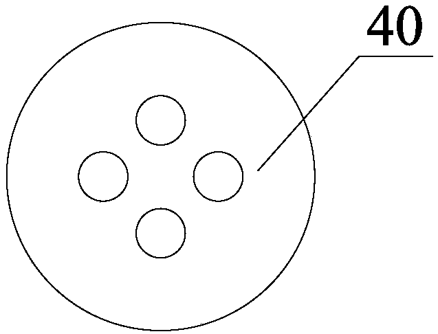
[0072] There are 4 hydrocarbon oil I outer spray holes 40 on the hydrocarbon oil I outer spray head 1 described in Example 1, arranged uniformly on the hydrocarbon oil I outer spray head 1, and the diameter of each spray hole is 1.0mm.

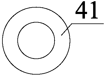
[0073] One hydrocarbon oil I inner spray hole 41 is provided on the hydrocarbon oil I inner spray head 4 described in Example 1, and the diameter of the spray hole on the hydrocarbon oil I inner spray head 4 is 1.1 mm.

[0074] Four hydrocarbon oil II injection holes 42 on the hydrocarbon oil II nozzle 7 described in Example 1 are arranged evenly on the hydrocarbon oil II nozzle 7, and the diameter of each injection hole is 0.6mm.

[0075] Four hydrocarbon oil III injection holes 43 are arranged on the hydrocarbon oil III nozzle 10 described in Example 1, and are evenly arranged on the hydrocarbon oil III nozzle 10, and the diameter of each injection hole is 0.6 mm.

[0076] The distance D between the hydrocarbon oil I inner spray head 4 and t...

Embodiment 2

[0094] There are three hydrocarbon oil I outer spray holes 40 on the hydrocarbon oil I outer spray head 1 described in Example 2, which are evenly arranged on the hydrocarbon oil I outer spray head 1, and the diameter of each spray hole is 1.1 mm.

[0095] One hydrocarbon oil I inner spray hole 41 is provided on the hydrocarbon oil I inner spray head 4 described in Example 2, and the diameter of the spray hole on the hydrocarbon oil I inner spray head 4 is 1.2 mm.

[0096] Two hydrocarbon oil II injection holes 42 on the hydrocarbon oil II nozzle 7 described in Example 2 are arranged evenly on the hydrocarbon oil II nozzle 7, and the diameter of each injection hole is 1.1 mm.

[0097] Two hydrocarbon oil III injection holes 43 are provided on the hydrocarbon oil III nozzle 10 described in Example 2, and are evenly arranged on the hydrocarbon oil III nozzle 10, and the diameter of each injection hole is 1.1 mm.

[0098] The distance D between the hydrocarbon oil I inner spray h...

Embodiment 3

[0116] One hydrocarbon oil I outer spray hole 40 on the hydrocarbon oil I outer spray head 1 described in Example 3 is arranged uniformly on the hydrocarbon oil I outer spray head 1, and the diameter of each spray hole is 2 mm.

[0117] One hydrocarbon oil I inner spray hole 41 is provided on the hydrocarbon oil I inner spray head 4 described in Example 3, and the diameter of the spray hole on the hydrocarbon oil I inner spray head 4 is 1.3 mm.

[0118] Three hydrocarbon oil II injection holes 42 on the hydrocarbon oil II nozzle 7 described in Example 3 are arranged uniformly on the hydrocarbon oil II nozzle 7, and the diameter of each injection hole is 0.8mm.

[0119] Three hydrocarbon oil III injection holes 43 are provided on the hydrocarbon oil III nozzle 10 described in Example 3, arranged evenly on the hydrocarbon oil III nozzle 10, and the diameter of each injection hole is 0.8mm.

[0120] The distance D between the hydrocarbon oil I inner spray head 4 and the hydrocarb...


PUM

PropertyMeasurementUnit
diameteraaaaaaaaaa
boiling pointaaaaaaaaaa

Abstract

The invention relates to a spray nozzle for catalytic cracking and an application. The spray nozzle can simultaneously spray three raw materials and comprises a hydrocarbon oil I outer sleeve pipe, ahydrocarbon oil I inner sleeve pipe, a hydrocarbon oil I outer spray head, a hydrocarbon oil I inner spray head, a steam chamber, a hydrocarbon oil I and steam mixing chamber, a hydrocarbon oil II spray head, a hydrocarbon oil III spray head, a hydrocarbon oil II semi-circular atomizing chamber and a hydrocarbon oil III semicircular atomizing chamber. The spray nozzle can be used in a catalytic cracking lift pipe device which successively comprises a light hydrocarbon reaction zone I, a heavy hydrocarbon reaction zone and a light hydrocarbon reaction zone II from bottom to top along the axis of a reactor. According to the invention, through arrangement of the hydrocarbon oil II semi-circular atomizing chamber and the hydrocarbon oil III semi-circular atomizing chamber on the spray nozzle,the spray nozzle provided by the invention can simultaneously spray three raw materials, and can be used for experimental study of simultaneous contact and reaction of different catalytic raw materials with a catalyst;; and light hydrocarbons sprayed by the hydrocarbon oil II spray head and the hydrocarbon oil III spray head preferentially contact with the catalyst for a reaction to generate a large amount of carbonium ions, so conversion of heavy hydrocarbons is accelerated, and the spray nozzle provided by the invention has the characteristic of increasing the yield of gasoline.

Description

technical field [0001] The invention relates to a catalytic cracking conversion device for petroleum hydrocarbons, more specifically, to a catalytic cracking nozzle and its application. Background technique [0002] As the main light oil production process in the oil refining industry, catalytic cracking has attracted extensive attention from major research and development institutions at home and abroad because of its wide applicability and relatively low processing cost. Catalytic cracking provides 75% of gasoline components in my country's commercial gasoline pool, and plays a pivotal role in refineries. In the process of catalytic cracking process and catalyst research and development, the catalytic cracking test device is used in the screening of catalytic cracking catalyst formula, the investigation of catalytic raw material cracking performance and product properties, the evaluation of catalytic cracking catalyst, the optimization and simulation of reaction process co...

Claims


Application Information

Patent Timeline
Patent Type & Authority Applications(China)
IPC IPC(8): C10G11/00B05B1/14B05B7/06
CPCB05B1/14B05B7/061C10G11/00C10G2300/1037C10G2400/02
Inventor 侯凯军高永福王智峰高雄厚李荻孙雪芹孟凡芳张海涛刘超伟柳召永
Owner PETROCHINA CO LTD
Why Eureka
Try Eureka