Spray nozzle for catalytic cracking lift pipe and application
A catalytic cracking and riser technology, applied in catalytic cracking, cracking, petroleum industry and other directions, can solve the problem of inability to simulate the spray contact and reaction of heavy diesel oil, and achieve the effects of simple structure, uniform contact and convenient use.
- Summary
- Abstract
- Description
- Claims
- Application Information
AI Technical Summary
Problems solved by technology
Method used
Image
Examples
Embodiment 1
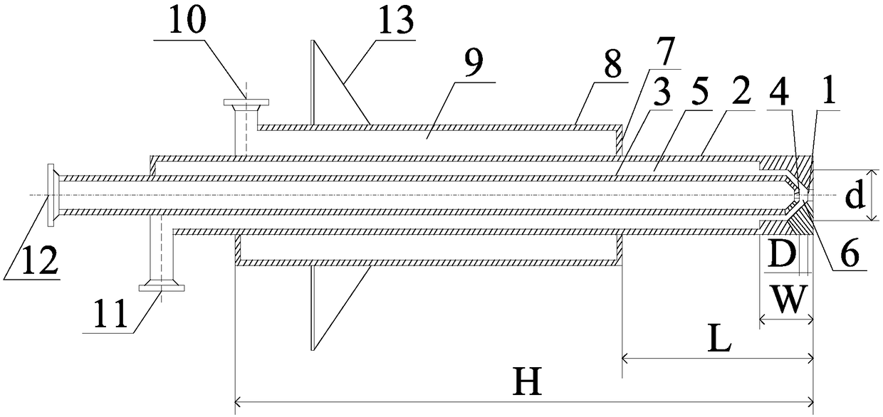
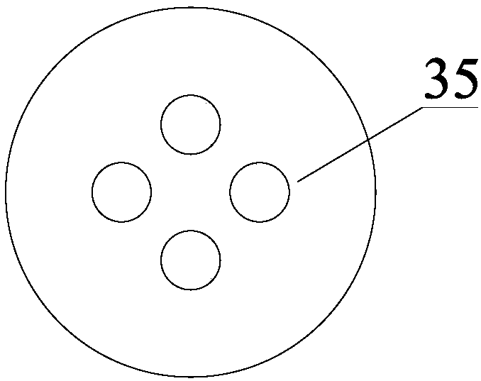
[0062] There are 4 hydrocarbon oil I outer spray holes 35 on the hydrocarbon oil I outer spray head 1 described in Example 1, which are evenly arranged on the hydrocarbon oil I outer spray head 1, and the diameter of each spray hole is 0.7 mm.
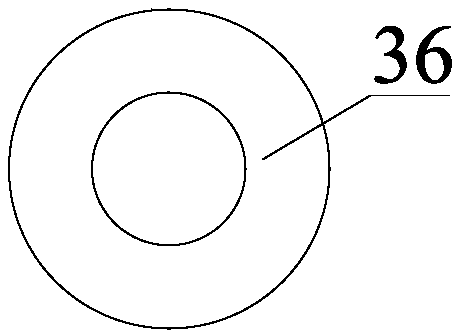
[0063] One hydrocarbon oil I inner spray hole 36 is provided on the hydrocarbon oil I inner spray head 4 described in Example 1, and the diameter of the spray hole on the hydrocarbon oil I inner spray head 4 is 1.1 mm.
[0064] Four hydrocarbon oil II nozzle holes 37 on the hydrocarbon oil II nozzle 7 described in Example 1 are arranged evenly on the hydrocarbon oil II nozzle 7, and the diameter of each nozzle hole is 1.0 mm.
[0065] The distance D between the hydrocarbon oil I inner spray head 4 and the hydrocarbon oil I outer spray head 1 described in Example 1 is 3 mm.
[0066] The reduced diameter d of the steam chamber 5 described in Example 1 is 4.5mm.
[0067] The ratio of the distance L between the hydrocarbon oil II nozzle 7...
Embodiment 2
[0077] There are two hydrocarbon oil I outer spray holes 35 on the hydrocarbon oil I outer spray head 1 described in Example 2, which are evenly arranged on the hydrocarbon oil I outer spray head 1, and the diameter of each spray hole is 1.1 mm.
[0078] One hydrocarbon oil I inner spray hole 36 is provided on the hydrocarbon oil I inner spray head 4 described in Example 2, and the diameter of the spray hole on the hydrocarbon oil I inner spray head 4 is 1.2 mm.
[0079] Four hydrocarbon oil II nozzle holes 37 on the hydrocarbon oil II nozzle 7 described in Example 2 are arranged evenly on the hydrocarbon oil II nozzle 7, and the diameter of each nozzle hole is 1.1 mm.
[0080] The distance D between the hydrocarbon oil I inner spray head 4 and the hydrocarbon oil I outer spray head 1 described in Example 2 is 3.5 mm.
[0081] The reduced diameter d of the steam chamber 5 described in Example 2 is 4.6 mm.
[0082] The ratio of the distance L between the hydrocarbon oil II nozzl...
Embodiment 3
[0092] One hydrocarbon oil I outer spray hole 35 on the hydrocarbon oil I outer spray head 1 described in Example 3 is arranged uniformly on the hydrocarbon oil I outer spray head 1, and the diameter of each spray hole is 2mm.
[0093] One hydrocarbon oil I inner spray hole 36 is provided on the hydrocarbon oil I inner spray head 4 described in Example 3, and the diameter of the spray hole on the hydrocarbon oil I inner spray head 4 is 1.3 mm.
[0094] Six hydrocarbon oil II injection holes 37 on the hydrocarbon oil II nozzle 7 described in Example 3 are arranged evenly on the hydrocarbon oil II nozzle 7, and the diameter of each injection hole is 0.9mm.
[0095] The distance D between the hydrocarbon oil I inner spray head 4 and the hydrocarbon oil I outer spray head 1 described in Example 3 is 4mm.
[0096] The reduced diameter d of the steam chamber 5 described in Example 3 is 4.7mm.
[0097] The ratio of the distance L between the hydrocarbon oil II nozzle 7 and the hydro...
PUM
 Abstract
Description
Claims
Application Information
 - R&D
- Intellectual Property
- Life Sciences
- Materials
- Tech Scout
- Unparalleled Data Quality
- Higher Quality Content
- 60% Fewer Hallucinations
Browse by: Latest US Patents, China's latest patents, Technical Efficacy Thesaurus, Application Domain, Technology Topic, Popular Technical Reports.
© 2025 PatSnap. All rights reserved.Legal|Privacy policy|Modern Slavery Act Transparency Statement|Sitemap|About US| Contact US: help@patsnap.com


