Intelligent lock with dehumidification function
A technology of smart locks and functions, applied in the field of smart locks, can solve problems such as user inconvenience, damage to electronic components, leakage of electricity, etc., to improve functionality and reliability, improve service life, and prevent moisture damage.
- Summary
- Abstract
- Description
- Claims
- Application Information
AI Technical Summary
Problems solved by technology
Method used
Image

Examples
Embodiment Construction
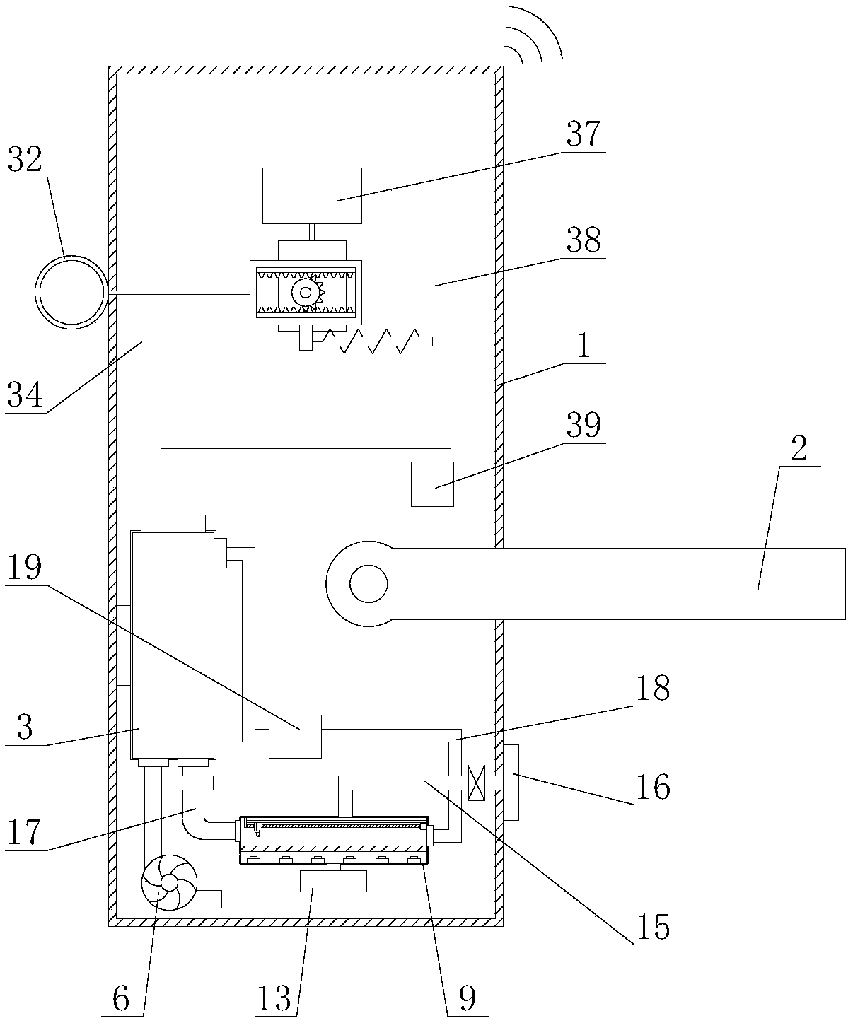
[0029] The present invention is described in further detail now in conjunction with accompanying drawing. These drawings are all simplified schematic diagrams, which only illustrate the basic structure of the present invention in a schematic manner, so they only show the configurations related to the present invention.
[0030] Such as figure 1 As shown, a smart lock with dehumidification function includes a lock case 1 and a handle 2, and also includes a dehumidification mechanism and an auxiliary mechanism, and the dehumidification mechanism and the auxiliary mechanism are both arranged in the lock case 1;
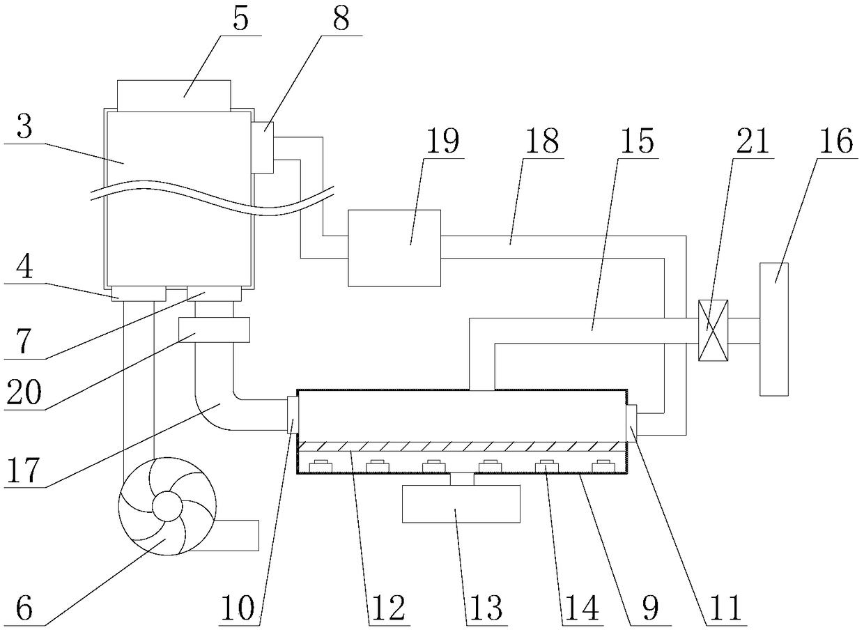
[0031] Such as Figure 2-3 As shown, the dehumidification mechanism includes a ventilation component and a processing component, and the processing component is arranged in the ventilation component;
[0032] The ventilation assembly includes a drying unit, a dehumidification unit and a material delivery unit, and the drying unit is connected with the dehumidification ...
PUM
 Abstract
Description
Claims
Application Information
 - Generate Ideas
- Intellectual Property
- Life Sciences
- Materials
- Tech Scout
- Unparalleled Data Quality
- Higher Quality Content
- 60% Fewer Hallucinations
Browse by: Latest US Patents, China's latest patents, Technical Efficacy Thesaurus, Application Domain, Technology Topic, Popular Technical Reports.
© 2025 PatSnap. All rights reserved.Legal|Privacy policy|Modern Slavery Act Transparency Statement|Sitemap|About US| Contact US: help@patsnap.com