Shifting force detecting, positioning and clamping device of gear pawl lever, and shifting force detection and correction method of gear pawl lever

A technology of positioning clamping and shifting force, which is applied in the direction of measuring device, workpiece clamping device, force/torque/power measuring instrument, etc., can solve the problems of inequal application and different shifting force, and avoid the process long-term effect

Active Publication Date: 2019-02-26
山东帝胜变速器有限公司
View PDF6 Cites 2 Cited by
  • Summary
  • Abstract
  • Description
  • Claims
  • Application Information

AI Technical Summary

Problems solved by technology

[0009] The second technical problem to be solved is: this is because the pawl spring of the gearbox is different from that of the shifter, and due to the difference in the elastic physical properties of the pawl spring itself, each pawl spring has the same deformation. Under the premise, the shifting forces generated are not the same, so the same displacement or torque will be generated by the gear change, and the detection probe can be used to judge whether the position is in place, and then the gear can be judged by whether the probe can be touched. There are differences in whether the shifting force of the claw lever meets the requirements, and it cannot be equivalently applied

Method used


Image

  • Shifting force detecting, positioning and clamping device of gear pawl lever, and shifting force detection and correction method of gear pawl lever
  • Shifting force detecting, positioning and clamping device of gear pawl lever, and shifting force detection and correction method of gear pawl lever
  • Shifting force detecting, positioning and clamping device of gear pawl lever, and shifting force detection and correction method of gear pawl lever

Examples


specific Embodiment approach

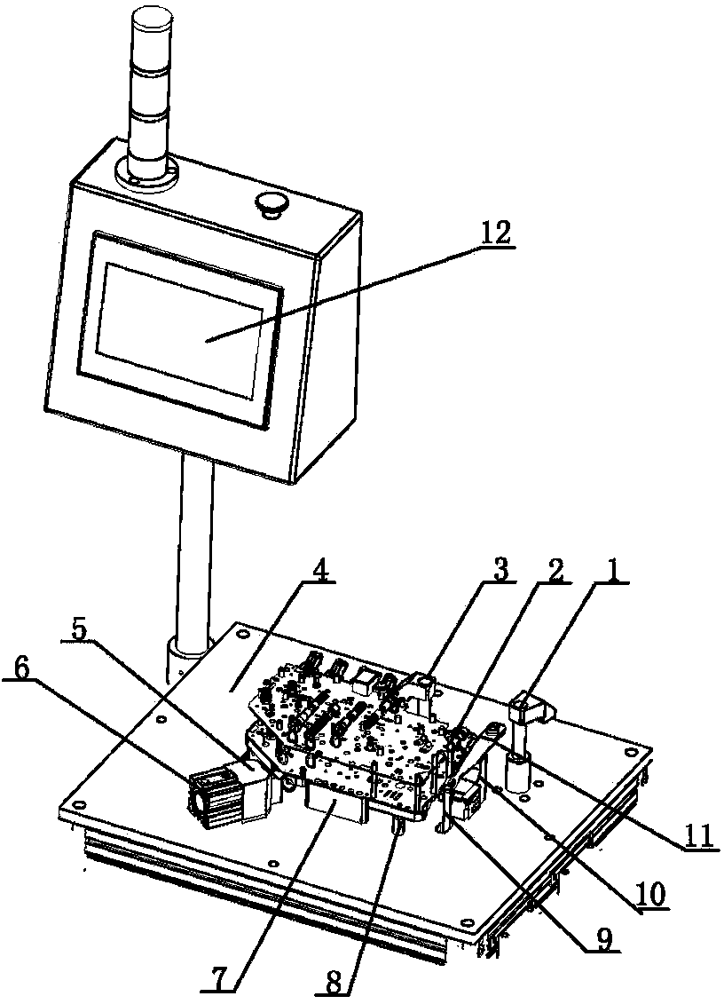
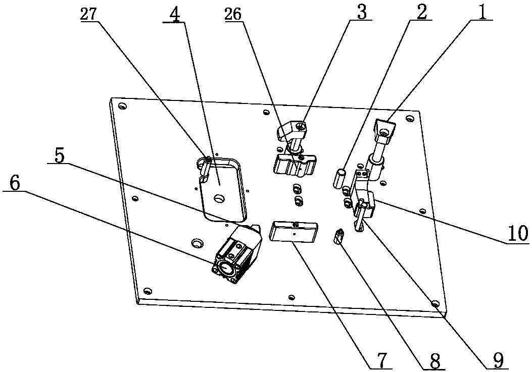
[0041]Put the valve body on the operation platform of the pawl piece selection machine, use the left positioning pin 27, the lower positioning block 7, the upper positioning block 26, the right positioning column 2 and the lower positioning pin 8 on the platform to provide positioning for the valve body assembly , to limit the degree of freedom of the valve body in the horizontal direction. At this time, the shift force test rod 9 is just below the card wheel 24 at the tail end of the pawl spring assembly, and the six variable flow solenoid valves 15 are just located in the concave of the variable flow solenoid valve. In slot 4;

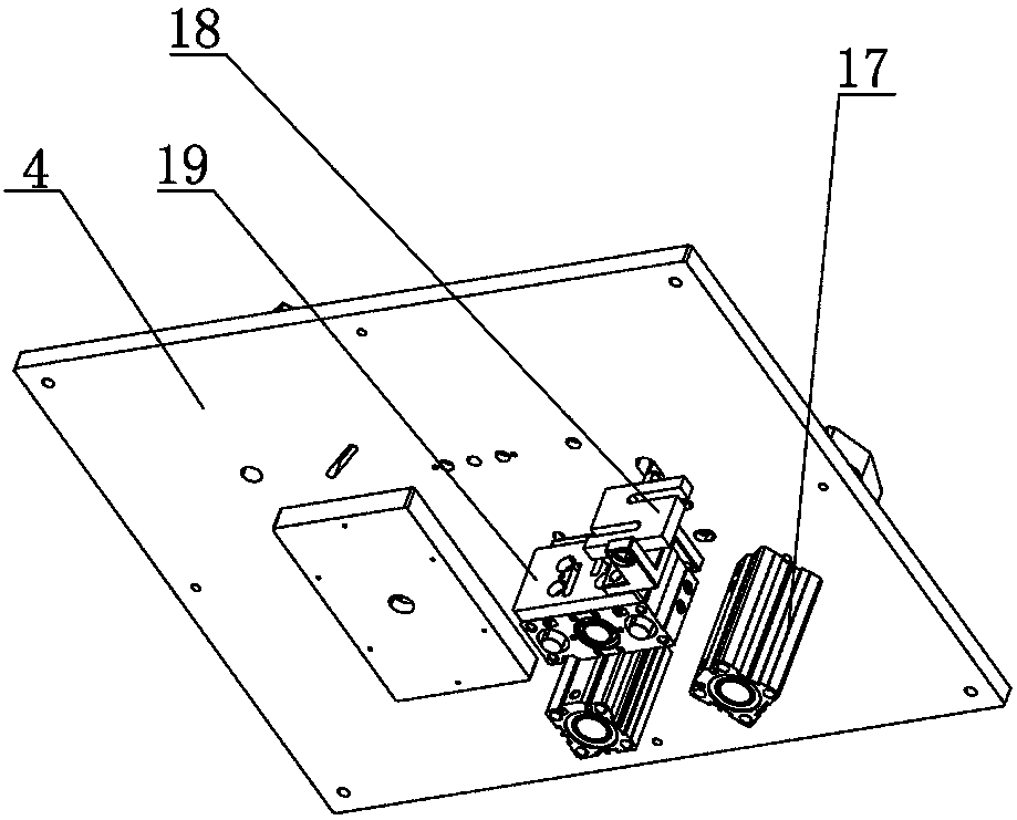
[0042] Press the two start buttons at the same time, the clamping claw 3 of the valve body assembly will rotate clockwise 90° under the action of the lower rotary clamping cylinder 25 and move downward at the same time, pressing the upper part of the valve body, and the valve body assembly pushes the block 5 Driven by the action of the cylinder, move...

Embodiment approach 1

[0045] If the feedback elastic force is within the range of 39.5±0.5N, it is qualified. The pressing claw 3 of the valve body assembly, the clamping claw 1 of the ratchet spring assembly, and the pushing block 5 of the valve body assembly return to the initial position under the action of the corresponding control cylinder. Lift up the valve body assembly and move to the next station;

Embodiment approach 2

[0047] If the feedback elastic force is within the range of 38-39N, if it is unqualified, the pressing claw 3 of the valve body assembly, the clamping claw 1 of the ratchet spring assembly, and the pushing block 5 of the valve body assembly will return to the initial state under the action of the corresponding control cylinder Position, lift the valve body assembly, reduce the adjustment gasket 4.5mm to 4mm, repeat the above test process, the feedback elastic force is within the range of 39.5±0.5N, qualified;


PUM


Abstract

The invention discloses a shifting force detecting, positioning and clamping device of a gear pawl lever, and a shifting force detection and correction method of a gear pawl lever, characterized in that the invention comprises a shifting force detecting, positioning and clamping device of a gear pawl lever, a shifting force detection method of a gear pawl lever by using the device, and a shiftingforce correction method of a gear pawl lever by using feedback of elastic force parameters in the shifting force detection method of the gear pawl lever. The invention has the beneficial effects thatthe shifting force detecting, positioning and clamping device of a gear pawl lever is cooperated with a shift force test lever through a pawl spring assembly, the shifting force of the gear pawl leveris converted into pressure of a force sensor between the shifting force test lever and a cylinder below and the pressure is taken as a basic quantification parameter, the accurate quantification is realized, and a pawl spring with different specificity and the elastic physical property is accurately corrected based on the basic quantization parameter of the pressure, thereby avoiding long processing time caused by multiple corrections and avoiding wasting manpower and material resources.

Description

technical field [0001] The invention belongs to the technical field of auto parts detection devices, and more specifically relates to a shift force detection, positioning and clamping device of a gear pawl lever and a method for detecting and correcting the shift force of a gear pawl lever. Background technique [0002] The shift force is the resistance felt by the driver when he toggles the joystick when the car shifts gears. The magnitude of the shifting force directly affects the user's experience when shifting gears. A good shifting force can bring better human-computer interaction and improve the user's driving experience. [0003] The factors affecting the shifting force of the whole package are mainly the shifting force of the shifter and the shifting force of the gear pawl lever, so the comprehensive shifting force is the combined effect of the shifting force of the shifter and the shifting force of the gear pawl lever the result of. [0004] When shifting gears, t...

Claims


Application Information

Patent Timeline
Patent Type & Authority Applications(China)
IPC IPC(8): G01L5/22B25B11/00
CPCB25B11/00G01L5/223
Inventor 李俊扬杨成滨陈先政刘小东
Owner 山东帝胜变速器有限公司
Why Eureka
Try Eureka