Lens system

A lens system and lens technology, applied in the field of lens systems, can solve the problems of complex installation and processing, not meeting the aesthetic requirements of consumers, etc., and achieve the effects of easy processing and installation, improving user experience, and wide application range.

Inactive Publication Date: 2019-02-26
北京五环伟业科技有限公司
View PDF4 Cites 2 Cited by
  • Summary
  • Abstract
  • Description
  • Claims
  • Application Information

AI Technical Summary

Problems solved by technology

However, most of the flexible zoom lenses in the prior art need to be fixed by the frame as a whole. For example, they can only be used in full-frame glasses, which do not meet the aesthetic requirements of consumers, and the installation and processing are complicated, which cannot meet the increasing needs of people.

Method used


Image

  • Lens system
  • Lens system
  • Lens system

Examples


Embodiment 1

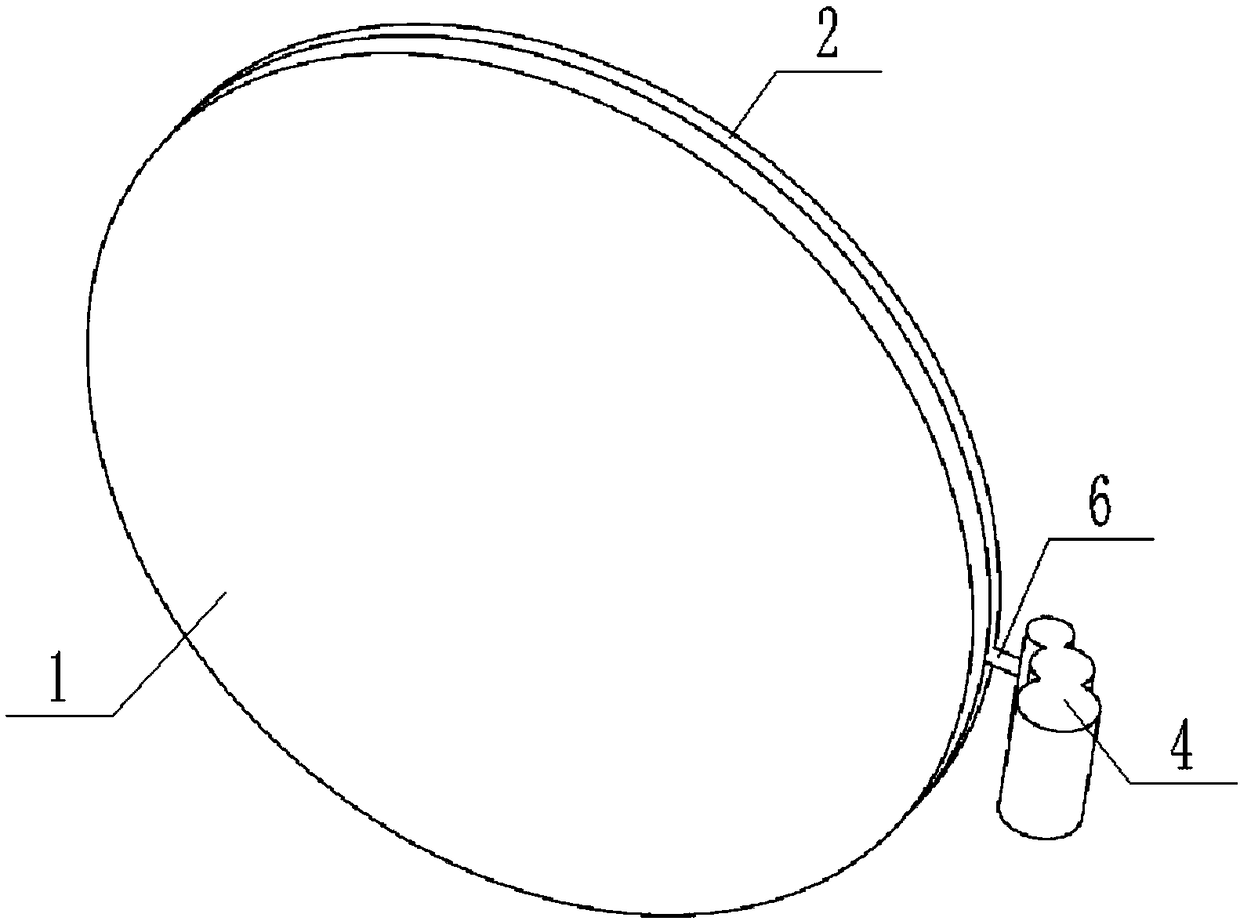
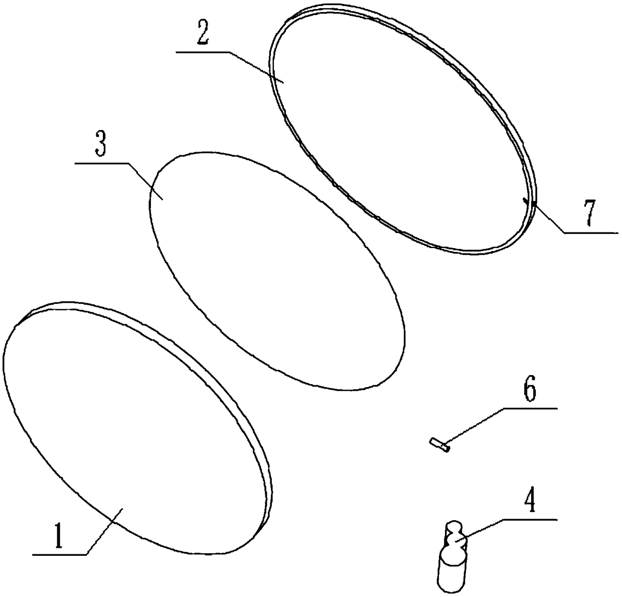
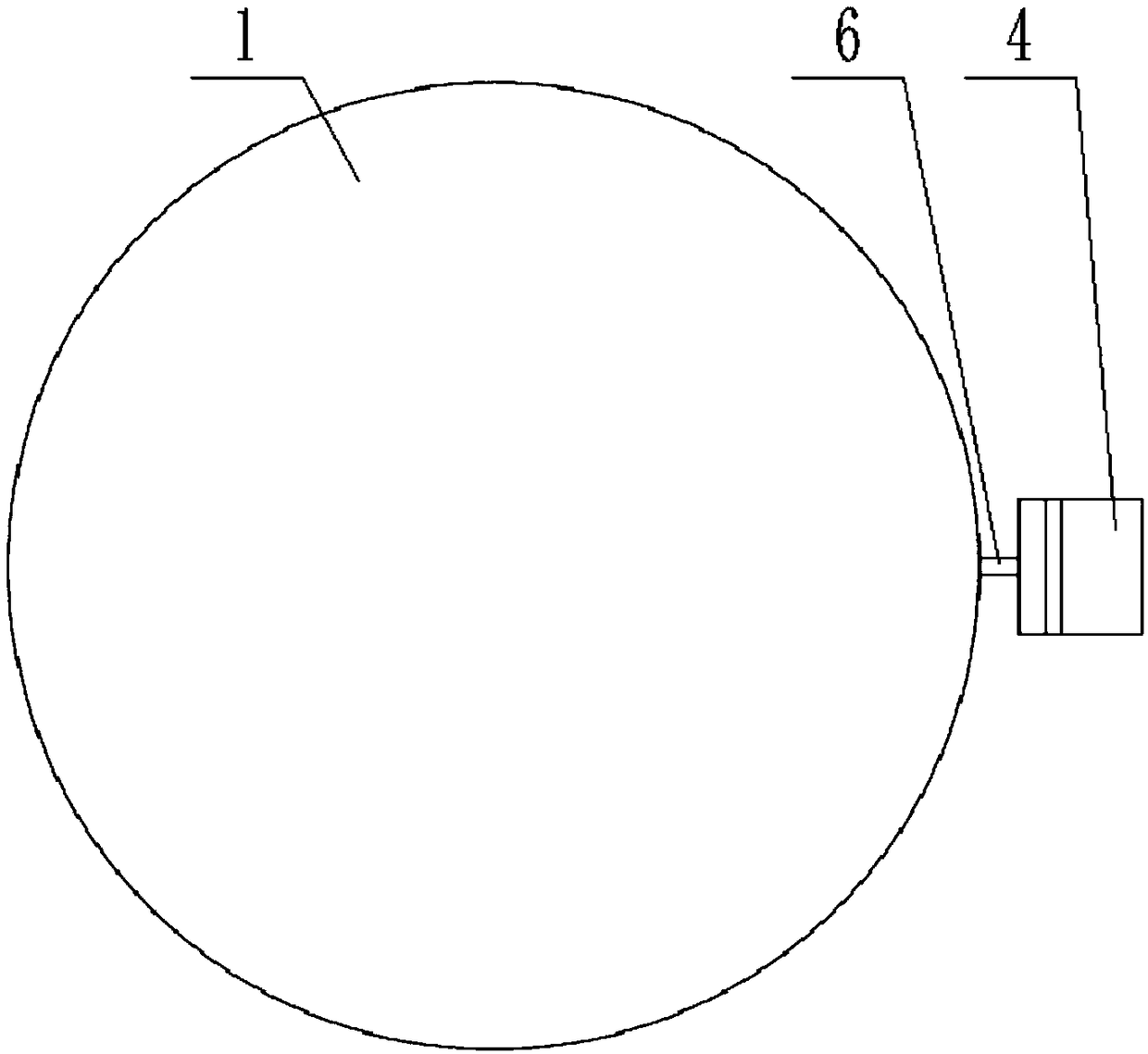
[0040] figure 1 , figure 2 , image 3 They are the structure diagram, explosion diagram and plan diagram of the lens system provided by Embodiment 1 of the present invention, respectively. combine figure 1 , figure 2 and image 3 Shown:

[0041] The lens system provided by Embodiment 1 of the present invention includes: a substrate 1 , an attachment 2 , a transparent fluid 3 , a pressure regulator 4 and a conduit 6 . Wherein, the edge of the substrate 1 and the attachment 2 is connected, the transparent fluid 3 is filled between the substrate 1 and the attachment 2, the pressure regulator 4 increases or decreases the filling pressure of the transparent fluid 3 through the conduit 6, and changes the pressure of the substrate. 1 and the volume of the transparent fluid 3 in the closed cavity (not shown) formed between the attached sheet 2, and then change its pressure on the substrate 1 and the attached sheet 2, so that the substrate 1, the transparent fluid 3 and the Th...

Embodiment 2

[0059] figure 1 , figure 2 , image 3 They are the structure diagram, explosion diagram and plan diagram of the lens system provided by Embodiment 2 of the present invention, respectively. combine figure 1 , figure 2 and image 3 Shown:

[0060] The lens system provided by the second embodiment of the present invention includes: a substrate 1 , an attachment 2 , a transparent fluid 3 , a pressure regulator 4 and a conduit 6 . Wherein, the edge of the substrate 1 and the attachment 2 are connected, the transparent fluid 3 is filled between the substrate 1 and the attachment 2, the pressure regulator 4 increases or decreases the filling pressure of the transparent fluid 3 through the conduit 6, and changes the pressure of the substrate. The volume of the transparent fluid 3 in the closed cavity formed between 1 and the attached sheet 2, and then change its pressure on the substrate 1 and the attached sheet 2, so that the combination of the substrate 1, the transparent fl...


PUM


Abstract

The embodiment of the invention relates to a lens system. The lens system comprises a substrate, an attached piece, transparent fluid and a pressure adjustor; the substrate and the attached piece arelenses with focal power and of gradational non-spherical shapes; and the attached piece can produce corresponding shape change along the change of the borne pressure; the substrate and the attached piece are connected by adopting a splicing way of hot-melting or optical gluing, or integrated and connected by adopting a molding in one technology; an enclosed cavity is formed between the substrate and the attached piece so as to adjust the volume of the transparent fluid; the pressure adjustor enables the volume of the transparent fluid in the enclosed cavity to change by changing the filling pressure of the transparent fluid, thereby enabling various surfaces of the lens system to deform; the optical characteristic is presented that the entire focal length is changed, and the zooming is realized; the lens system disclosed by the embodiment of the invention can be suitable for various optical instrument equipment so as to realize the zooming, the variation and like optical functions; theinstrument is small in volume, high in performance and low in cost.

Description

technical field [0001] The invention relates to the technical field of optical devices, in particular to a lens system. Background technique [0002] Traditional zoom optical lens systems are usually composed of several optical components (lenses) with fixed focal lengths, relying on the forward and backward movement of the components to adjust the focal length of the system, or to achieve bifocal and progressive zoom on one lens, such as bifocal and progressive type lenses. [0003] The lens system composed of several optical components (lenses) has high requirements on the precision of mechanical positioning and moving parts. The entire zoom system has complex structure, high energy consumption of the drive system, large volume and weight, and high manufacturing cost. [0004] For example, the lenses of bifocal glasses are composed of upper and lower lenses with different focal lengths. The upper half is suitable for seeing far away, and the lower half is suitable for see...

Claims


Application Information

Patent Timeline
IPC IPC(8): G02C7/08G02B3/14
Inventor 邵秋峰赵富全任世民张佳佳才学武
Owner 北京五环伟业科技有限公司
Why Eureka
Try Eureka