
Liquid removing device of optical film

An optical film and angle adjustment technology, which is applied in the field of optical film, can solve the problems of non-reducing defects, rising costs, and inability to completely remove liquid, so as to improve applicability and maintainability, and ensure optical characteristics.

Active Publication Date: 2015-09-09
NITTO DENKO CORP
View PDF10 Cites 3 Cited by
  • Summary
  • Abstract
  • Description
  • Claims
  • Application Information

AI Technical Summary

Problems solved by technology

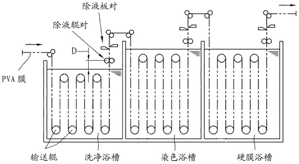
[0012] Since the liquid removal device is provided for each bath, installation work and maintenance work are inconvenient, resulting in increased costs
In addition, there is a defect that the liquid removal device (such as a liquid removal plate) cannot be adjusted according to the type, moving speed, and thickness of the polarizer
[0013] In addition, in addition to the liquid removal device of Patent Document 2, methods for removing liquid by using an air knife or nip rolls are also disclosed in the prior art, but these methods also have defects caused by the precipitation of boric acid adhering to the surface of the polarizer. Disadvantages that the phenomenon does not reduce and cannot completely remove the liquid

Method used


Image

  • Liquid removing device of optical film
  • Liquid removing device of optical film
  • Liquid removing device of optical film

Examples


no. 1 example

[0132] Such as Figure 12 As shown, in the liquid removal device of the first embodiment, the first liquid removal mechanism and the second liquid removal mechanism are respectively fixed at a predetermined distance from the polarizer with respect to the polarizer moving in the up and down direction (the first specified distance). An example of distance). This fixing method is beneficial to the situation where the installation place of the liquid removal device is relatively narrow. In the case of the composition of the first embodiment, the liquid removal device adjusts the angles of the plate parts of the first liquid removal mechanism and the second liquid removal mechanism to move the plate parts toward the polarizer in the standby state (such as Figure 12 (shown by the black dotted line in the up and down direction), and then before the water removal process starts, loosen the fixing bolt or the holding mechanism shaft fastening bolt to adjust the holding mechanism shaf...

no. 2 example

[0135] The liquid removal device of the first embodiment is fixedly installed, and the liquid removal device of the second embodiment is as Figure 13 As shown, each of the first liquid removal mechanism and the second liquid removal mechanism also has a guide part provided under the angle adjustment table, an air cylinder (an example of a moving mechanism) connected to the guide part, and the guide part is provided on the upper side. At this time, the first liquid removal mechanism and the second liquid removal mechanism move back and forth (the front close to the polarizer and the rear away from the polarizer) along with the telescopic action of the cylinder. In this case, when the guide part abuts against the guide part stopper provided at the front end of the guide rail, that is, at the end close to the polarizer, or through the perception of a laser sensor or a proximity sensor provided on each angle adjustment table, The angle adjustment table on the guide rail can be st...

no. 3 example

[0141] The liquid removal device of the third embodiment is as Figure 14 As shown, different from the first embodiment and the second embodiment, one of the first liquid removal mechanism and the second liquid removal mechanism adopts the composition of the first embodiment, while the other liquid removal mechanism adopts the second embodiment The composition of the example.

[0142] In addition, the pressing force of the plate member of the liquid removal device on the polarizer is set in advance in consideration of water removal performance, damage to the polarizer, and the like. If the degree of contact between the plate member and the polarizer is weak, the dewatering property will be reduced, causing problems. If the degree of contact is too strong, the polarizer will be damaged. In this case, the worst case is that the polarizer is broken. Therefore, if Figure 15 As shown, in order to make the pressing force of the plate member on the polarizer reach the set value, t...


PUM


Abstract

 Droplets adhering to the surface of an optical film are completely removed prior to a drying treatment step, optical characteristics and the like of the optical film are ensured, and applicability and ease of maintenance are high. A device for removing droplets is provided with: a draining member provided with a first draining mechanism and a second draining mechanism vertically staggered along the movement direction of the optical film and arranged on the left and right sides of the optical film, both the first draining mechanism and the second draining mechanism removing droplets; a draining-member-holding mechanism provided with a pressing-side member and a receiving-side member having an angle adjustment shaft protruding outward at both ends in the length direction, the pressing-side member and the receiving-side member being detachably secured so as to hold the draining member; and a pair of angle adjustment mechanisms for adjusting and securing the draining-member-holding mechanism so that the angle of the draining member relative to the optical film reaches a prescribed value, the pair of angle adjustment mechanisms being provided on both length-direction sides of the draining-member-holding mechanism, and the angle adjustment mechanisms being provided with a securing stand in which an angle adjustment shaft accommodation space is formed for accommodating at least the angle adjustment shaft.

Description

technical field [0001] The invention relates to an optical film, in particular to a liquid removal device for an optical film. Background technique [0002] Currently, liquid crystal display devices are widely used in clocks, mobile phones, PDAs, notebooks, monitors for computers, DVD players, TVs, and the like. A liquid crystal display device is a device that controls a liquid crystal to adjust a polarization state to realize visualization. According to the display principle, a polarizing film is used as an optical film. [0003] In particular, TVs and the like increasingly require high brightness, high contrast, and wide viewing angles. Therefore, polarizing films are increasingly required to have high transmittance, high polarization, and high color reproducibility. The polarizing film is generally produced by using a so-called water-based adhesive obtained by dissolving a polyvinyl alcohol-based material in water, and pasting a transparent protective film on both sides ...

Claims


Application Information

Patent Timeline
Patent Type & Authority Applications(China)
IPC IPC(8): B08B1/02B08B1/20
CPCF26B13/28G02B5/3033
Inventor 笠井政庆植敷大地奥村哲平
Owner NITTO DENKO CORP
Learn More