Shrinkage equipment with drying function for steel bar processing

A technology for steel bar processing and tools, which is applied in the field of shrinking equipment with drying function for steel bar processing. It can solve problems such as difficult removal of water, mixing of steel bars in the drum, and influence on steel bar disassembly, so as to prevent heat loss and increase moving speed. , The effect of speeding up the drying efficiency

Inactive Publication Date: 2020-06-05
南京六六创业科技有限公司
View PDF8 Cites 0 Cited by
  • Summary
  • Abstract
  • Description
  • Claims
  • Application Information

AI Technical Summary

Problems solved by technology

[0004] The purpose of the present invention is to provide a kind of shrinking equipment with drying function for steel bar processing, to solve the problem that the existing shrinking equipment for steel bar processing proposed in the above-mentioned background technology does not have drying function. A certain amount of moisture will remain on the steel bars, and the shrinking equipment will directly shrink the steel bars, causing the steel bars to be rolled together. The water is difficult to remove, resulting in rusting of the steel bars. The steel bars are mixed on the drum, which affects the disassembly of the steel bars from the drum in the later stage

Method used


Image

  • Shrinkage equipment with drying function for steel bar processing
  • Shrinkage equipment with drying function for steel bar processing
  • Shrinkage equipment with drying function for steel bar processing

Examples


Embodiment Construction

[0026] The following will clearly and completely describe the technical solutions in the embodiments of the present invention with reference to the accompanying drawings in the embodiments of the present invention. Obviously, the described embodiments are only some, not all, embodiments of the present invention. Based on the embodiments of the present invention, all other embodiments obtained by persons of ordinary skill in the art without making creative efforts belong to the protection scope of the present invention.

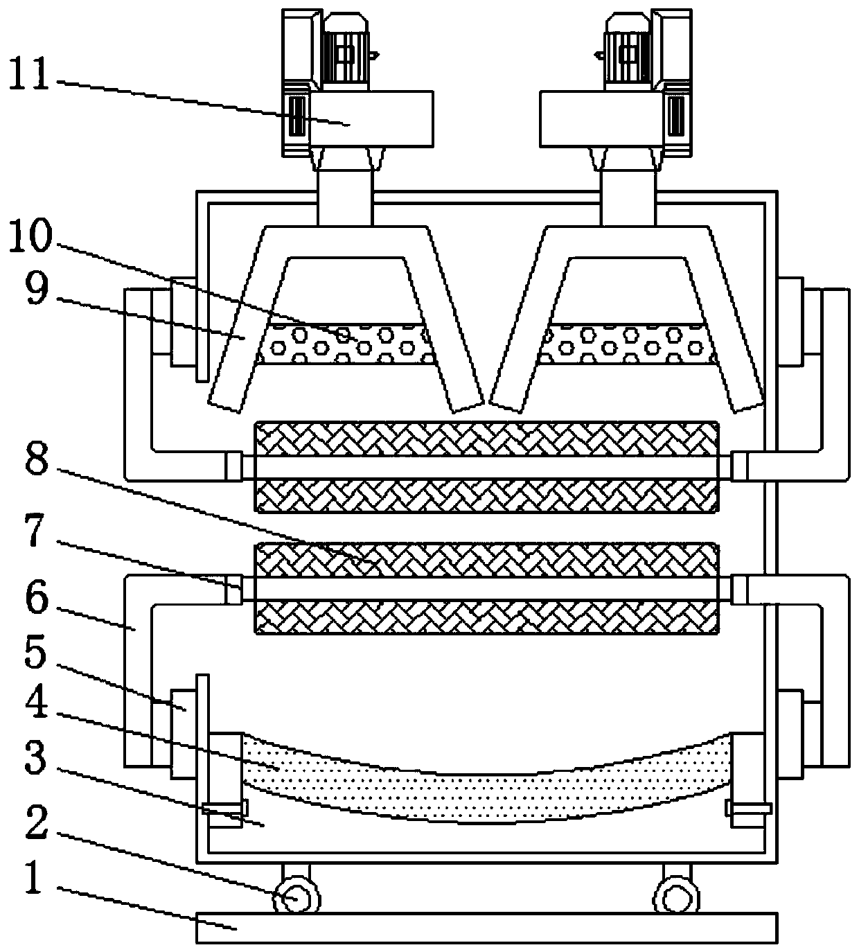
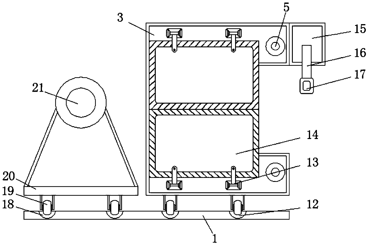
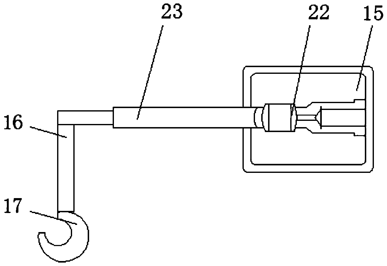
[0027] see Figure 1-5 , the present invention provides a technical solution: a shrinking equipment with drying function for steel bar processing, including a bottom plate 1, a first pulley 2, a drying box 3, a heat collecting plate 4, a first rotating shaft 5, and a connecting rod 6 , the second rotating shaft 7, the sponge rod 8, the air outlet 9, the heating net 10, the blower 11, the first chute 12, the door shaft 13, the door 14, the fixed box 15, the fix...


PUM


Abstract

The invention relates to contraction equipment with a drying function for steel bar machining. The contraction equipment comprises a punched bottom plate and first sliding grooves. First sliding wheels are arranged on the two sides of the upper end of the bottom plate, a drying box is placed at the upper ends of the first sliding wheels, a heat gathering plate is fixed to the bottom end inside thedrying box, first rotating shafts are mounted at the lower ends of the two sides of the drying box, connecting rods are inlaid at the ends, away from the central line of the drying box, of the firstrotating shafts, and the ends, close to the central line of the drying box, of the upper ends of the connecting rods are connected with second rotating shafts. The contraction equipment has the beneficial effects that heat emitted by the upper end inside the drying box can be gathered by the heat gathering plate at the lower end inside the drying box and reflected back, and the heat is gathered inthe middle of the inner side of the drying box, so that steel bars inside the drying box fully make contact with the heat, the drying efficiency of the steel bars can be improved, the heat loss can be further prevented, the heat generated in the drying box can be utilized maximally, and the flexibility of the contraction equipment is embodied.

Description

technical field [0001] The invention relates to the technical field of shrinking equipment for steel bar processing, in particular to a shrinking equipment with drying function for steel bar processing. Background technique [0002] Reinforcement bar is a kind of steel bar, which is a kind of building material. For example, in reinforced concrete, it is used to support the skeleton of the structure, including smooth round steel bar, ribbed steel bar and twisted steel bar. There are many types of steel bars, usually according to Chemical composition, production process, rolling shape, supply form, diameter, and use in the structure are classified. After the steel bar is produced, it needs to be rolled up for storage and transportation. [0003] The existing shrinking equipment for steel bar processing does not have a drying function. Since the steel bar will be cooled after production, a certain amount of moisture will remain on the steel bar. The shrinking equipment will dir...

Claims


Application Information

Patent Timeline
Patent Type & Authority Patents(China)
IPC IPC(8): B21C47/12B21C47/28B21C47/26F26B11/00F26B5/14F26B21/00F26B25/08F26B25/12
CPCB21C47/12B21C47/26B21C47/28F26B5/14F26B11/00F26B21/001F26B21/004F26B25/08F26B25/12
Inventor 郭亮
Owner 南京六六创业科技有限公司
Why Eureka
Try Eureka