
Novel efficient thermal field control polishing machine and polishing method thereof

A polishing machine and high-efficiency technology, used in grinding/polishing equipment, optical surface grinders, metal processing equipment, etc., can solve the problems of obvious heat accumulation effect of optical components, affecting the surface quality of optical components, affecting the processing surface shape of optical components, etc. , to achieve the effect of improving the surface shape convergence efficiency, reducing the heat accumulation phenomenon, and evenly distributing the polishing powder

Pending Publication Date: 2019-03-01
SHANGHAI INST OF OPTICS & FINE MECHANICS CHINESE ACAD OF SCI
View PDF9 Cites 3 Cited by
  • Summary
  • Abstract
  • Description
  • Claims
  • Application Information

AI Technical Summary

Problems solved by technology

Therefore, during the polishing process, the water on the polishing disc can only flow to the outside of the disc, resulting in uneven distribution of polishing powder on the entire disc (more inside, less on the edge), affecting the surface quality of optical components (defects); Due to the slow flow of water on the surface of the optical disc, the heat generated by friction is not dissipated in time, so that the heat accumulates in the middle of the polishing disc, and there is a temperature difference on the disc surface (the temperature in the middle of the disc is high, and the temperature at the edge is low). Processing Surface Shape of Optical Components

Method used


Image

  • Novel efficient thermal field control polishing machine and polishing method thereof
  • Novel efficient thermal field control polishing machine and polishing method thereof
  • Novel efficient thermal field control polishing machine and polishing method thereof

Examples


Embodiment 1

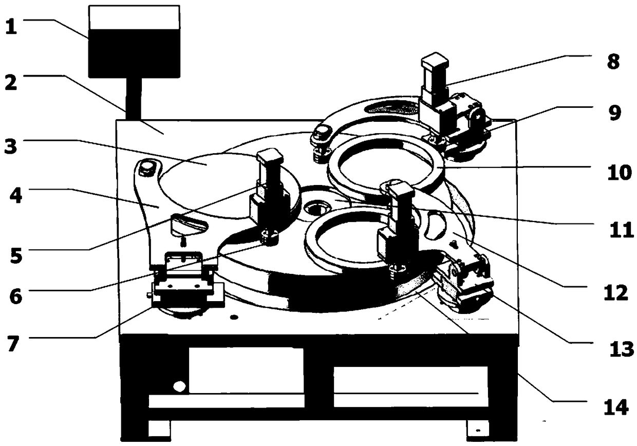
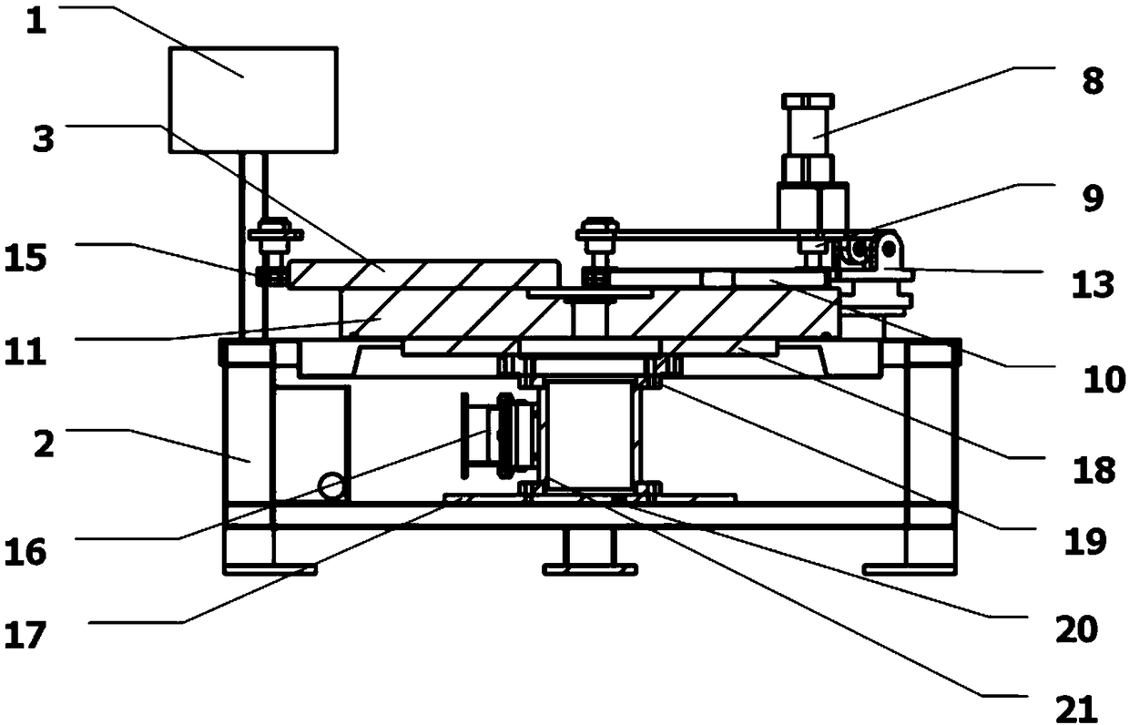
[0022] refer to figure 1 and figure 2 , figure 1 It is a structural schematic diagram of a novel high-efficiency thermal field control polishing machine of the present invention, figure 2 It is a sectional view of Embodiment 1 of the hollow marble disc polishing machine of the present invention. As can be seen from the figure, the present invention is a hollow marble disc polishing machine, which is characterized in that the polishing machine includes a control box 1, a frame 2, a calibration disc 3, a calibration disc pallet 4, a calibration disc drive motor 5, and a calibration disc drive wheel 6 , Calibration plate fixed base 7, workpiece ring drive motor 8, workpiece ring drive wheel 9, workpiece ring 10, hollow marble 11, workpiece ring supporting plate 12, workpiece ring base 13, water basin 14, correction disc wheel 15, motor 16. Lower supporting plate 17, tray 18, turntable bearing 19, water outlet 20 and cylindrical tray 21. Wherein, the diameter of the hollow s...

Embodiment 2~6

[0032] In Examples 2-6, the diameters of the hollow structures of the hollow marble 11 are respectively 1 / 4, 1 / 5, 1 / 6, 1 / 7 and 1 / 8 of the diameter of the polishing disc, and the hollow structures are all through holes. All the other structures and polishing methods are the same as in Example 1.


PUM


Abstract

The invention discloses a novel efficient thermal field control polishing machine and a polishing method thereof. The polishing machine comprises a controlling box, a machine frame, a correction disc,a correction disc supporting plate, a correction disc driving motor, a correction disc driving wheel, a correction disc fixing base, a workpiece ring driving motor, a workpiece ring driving wheel, workpiece rings, marble, a workpiece ring supporting plate, a workpiece ring base, a water basin, a correction disc wheel, a motor, a lower supporting plate, a tray, a rotating disc bearing and a wateroutlet. The marble is hollow. The invention further provides a polishing method of the novel efficient thermal field control polishing machine. The hollow marble disc is arranged, and therefore original one-way flowing of polishing liquid is changed into two-way flowing, flowing of the polishing liquid is accelerated, and therefore distribution of polishing powder on the surface of a polishing disc is uniform, and the surface quality of an optical element is improved. The surface thermal field distribution is uniform, heat accumulation during the polishing process is reduced, surface convergence efficiency is improved, and processing efficiency is improved.

Description

technical field [0001] The invention relates to optical element processing, in particular to a novel high-efficiency thermal field control polishing machine and a polishing method thereof. Background technique [0002] Planar optical components are generally polished by a traditional circular polishing machine. The traditional circular polishing machine uses a whole piece of marble as the polishing disc chassis, and pours asphalt polishing glue on it as a polishing mold, and digs in the center of the polishing glue. Empty a circular hole with a diameter of about 1 / 8-1 / 15 of the diameter of the polishing disc, and the circular hole is used to store water and polishing liquid. Therefore, during the polishing process, the water on the polishing disc can only flow to the outside of the disc, resulting in uneven distribution of polishing powder on the entire disc (more inside, less on the edge), affecting the surface quality of optical components (defects); Due to the slow flow ...

Claims


Application Information

Patent Timeline
Patent Type & Authority Applications(China)
IPC IPC(8): B24B13/00B24B13/01
CPCB24B13/00B24B13/01
Inventor 徐学科吴福林曹俊杨明红顿爱欢邵建达
Owner SHANGHAI INST OF OPTICS & FINE MECHANICS CHINESE ACAD OF SCI
Learn More