
Measuring device

A technology for measuring position and measuring head, applied in the direction of measuring device, mechanical measuring device, using mechanical device, etc., can solve problems such as affecting accuracy, and achieve the effect of prolonging processing cycle, low weight, and improving process control

Pending Publication Date: 2019-03-01
AGATHON
View PDF22 Cites 0 Cited by
  • Summary
  • Abstract
  • Description
  • Claims
  • Application Information

AI Technical Summary

Problems solved by technology

However, stopping the movement of the measuring head may generate vibrations that affect accuracy

Method used


Image

  • Measuring device

Examples


Embodiment Construction

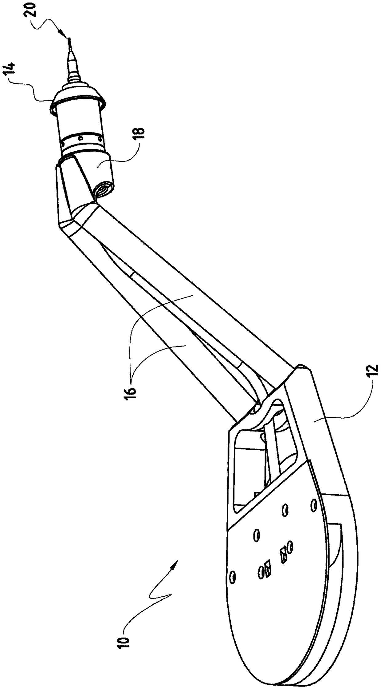
[0025] The measuring unit is in figure 1 is shown in and is denoted by "10" in its entirety. In this example, the measuring unit 10 is arranged in a machine tool, for example in a grinding machine. According to the invention, the measuring unit 10 is used for in-process measurement of a workpiece during a machining operation on a grinding machine. A grinding machine may have a grinding wheel fixed to the machine (grinding machine); the grinding wheel is rotatable about an axis of rotation and is used for machining workpieces. The measuring unit 10 comprises a base element 12 which may be arranged at a headstock (not shown) of the grinding machine so as to be pivotable about a pivot axis (not shown).

[0026]Furthermore, the measuring unit 10 comprises a measuring head 14 which is connected to the base element 12 of the measuring unit 10 by means of an arm 16 or more arms so as to be pivotable about a pivot axis. The measuring unit 10 also has means for pivoting the measurin...


PUM


Abstract

The present invention relates to a measuring unit (10) for in-process measurement during a machining operation on machine tool, in particular a grinding machine comprising at least a wheel head arranged at a headstock, comprising a measuring head (14), which is movable between a rest position and a measuring position, and means for moving the measuring head between the rest position and the measuring position. The measuring unit (10) is configured such that the rest position and the measuring position of the measuring head (14) are infinitely adjustable by a user by controlling the movement ofthe measuring head (14) between the rest position and the measuring position.

Description

technical field [0001] The invention relates to a measuring unit, in particular for in-process measuring during machining on machine tools, especially on grinding machines. Background technique [0002] Machine tools, especially grinding machines, are well known in the art. Furthermore, grinding machines generally comprise a workpiece unit, a tool unit, a measuring unit, and a control unit connectable to the measuring unit and the tool unit. Known measuring units or devices are provided for in-process measurements during machining, wherein the control program is integrated into the machining program to simplify the integration of the probe cycle with the machining operation, thereby reducing setup time . So-called in-process measurements, i.e. measurements taken during machining operations, enable high-precision machining operations and can help to increase manufacturing quality and process reliability. [0003] Productivity in precision part machining is increased by com...

Claims


Application Information

Patent Timeline
IPC IPC(8): B24B49/02
CPCB24B49/02B24B49/04G01B5/0004G01B5/012G01B5/08G01B5/201
Inventor C·博布斯特J·马蒂T·阿克曼
Owner AGATHON
Learn More