Vacuum suction material conveying pump system

A technology of vacuum suction and conveying pump, applied in conveyors, conveying bulk materials, transportation and packaging, etc., can solve the problems of high energy consumption and high construction cost

Pending Publication Date: 2019-03-01
CHINA RAILWAY ENGINEERING EQUIPMENT GROUP CO LTD
View PDF8 Cites 3 Cited by
  • Summary
  • Abstract
  • Description
  • Claims
  • Application Information

AI Technical Summary

Problems solved by technology

[0003] Aiming at the deficiencies described in the above-mentioned prior art, the present invention provides a vacuum suction conveying pump system for overcoming the existing problems of high construction cost and high energy consumption

Method used


Image

  • Vacuum suction material conveying pump system

Examples


Embodiment 1

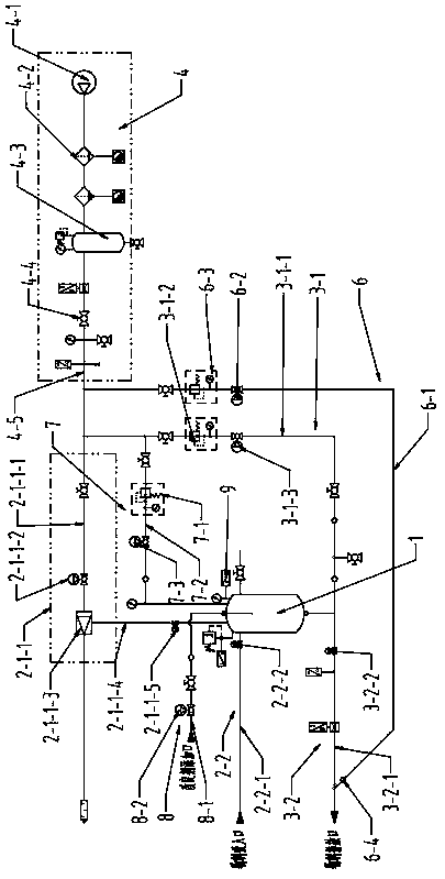
[0020] Embodiment 1: A vacuum suction conveying pump system, including a pressure vessel, a vacuum slag suction unit and a positive pressure slag discharge pumping unit; the vacuum slag suction unit sucks the slag into the pressure vessel through negative pressure, The pumping unit discharges the slag from the pressure vessel through positive pressure.

Embodiment 2

[0021] Embodiment 2: A vacuum suction conveying pump system, the vacuum slag suction unit includes a vacuum pumping assembly and a slag suction assembly, the vacuum pumping assembly includes a positive pressure generating component and a vacuum generating component, and the positive pressure generating component passes through The vacuum generating component communicates with the negative pressure suction port of the pressure vessel, the slag suction assembly includes a slag suction pipe and a pneumatic gate valve I; the slag suction pipe communicates with the slag inlet of the pressure vessel through the pneumatic gate valve I, and the positive pressure generating component , including air compressor, filter, air storage tank, manual ball valve, positive pressure pipeline Ⅰ; the positive pressure pipeline Ⅰ is equipped with air compressor, filter and air storage tank connected in sequence, and the positive pressure pipeline Ⅰ passes through the manual ball valve It communicate...

Embodiment 3

[0022] Embodiment 3: A vacuum suction conveying pump system, the positive pressure slag discharge pumping unit includes a positive pressure generating component, a positive pressure conveying component and a slag discharging component, and the positive pressure generated by the positive pressure generating component is conveyed through positive pressure The component is transported into the slag discharge assembly, the slag discharge port of the pressure vessel is connected with the slag discharge pipe of the slag discharge assembly, and the positive pressure generating components include air compressor, filter, gas storage tank, manual ball valve, positive pressure pipeline I The positive pressure pipeline I is provided with an air compressor, a filter and an air storage tank connected in sequence, and the positive pressure pipeline I communicates with the positive pressure pipeline III of the positive pressure delivery assembly through a manual ball valve, and the rest are the...


PUM


Abstract

The invention discloses a vacuum suction material conveying pump system. The vacuum suction material conveying pump system comprises a pressure container, a vacuum slag suction unit and a positive pressure deslagging pumping unit, wherein the vacuum slag suction unit sucks slag into the pressure container through negative pressure, the positive pressure deslagging pumping unit is used for discharging the slag from the pressure container through positive pressure. According to the system, the vacuum suction overcomes the problems that manual work cannot be carried out in an effective space andlifting muck is difficult in the effective space, pneumatic conveying is applied to a shield machine, and a new conveying method satisfies the construction requirement and the construction cost is reduced; the air erosion situation generated in a material conveying process of a centrifugal pump is overcome, so that a large amount of energy consumption of a plunger pump in a high-pressure conveyingmode in the conveying process is overcome, the loss and large particle material conveying difficulty are caused due to the fact that a stator and a rotor are abrased in the material conveying processof a screw rod is overcome; and the certain problems in engineering construction and industrial application are solved.

Description

technical field [0001] The present invention relates to the technical field of pneumatic control, and is especially applicable to discharge operations of various liquids and solids where the space of the site is limited and where dregs or wastes cannot be handled manually, especially for discharge of various dregs such as clay and powder transportation on the roadheader Vacuum suction conveying pump system. Background technique [0002] For the various roadheaders currently used in tunnel construction in China, the soil transfer method usually adopts the rear matching marshalling train method to carry the slag or transport the pumping medium to the corresponding pumping station on the roadheader equipment for pumping the slag. There are not many pumping options selected by this transportation method on high-viscosity media, which not only increases the construction cost, but also greatly reduces the construction efficiency. In the case of limited space, most equipment is li...

Claims


Application Information

Patent Timeline
Patent Type & Authority Applications(China)
IPC IPC(8): B65G53/46B65G53/24B65G53/34
CPCB65G53/24B65G53/34B65G53/46
Inventor 俞培德周小磊王双旺郭付军张凯朱英赵云辉张杰袁丹高可可刘晓瑞姚晶张龙飞陈建兴
Owner CHINA RAILWAY ENGINEERING EQUIPMENT GROUP CO LTD
Why Eureka
Try Eureka