Energy-saving tempering furnace

A tempering furnace and shell technology, applied in furnaces, heat treatment furnaces, furnace types, etc., can solve the problems of low heating efficiency of energy-saving tempering furnaces, achieve good heating effects, reduce time and energy, and improve sealing

Active Publication Date: 2019-03-01
江苏富捷刀业有限公司
View PDF5 Cites 8 Cited by
  • Summary
  • Abstract
  • Description
  • Claims
  • Application Information

AI Technical Summary

Problems solved by technology

[0004] The purpose of the present invention is to provide an energy-saving tempering furnace, which has the advantage of high heating efficiency and solves the problem of low heating efficiency of common energy-saving tempering furnaces

Method used


Image

  • Energy-saving tempering furnace
  • Energy-saving tempering furnace
  • Energy-saving tempering furnace

Examples


no. 1 approach

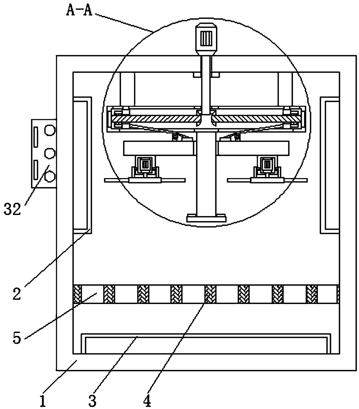
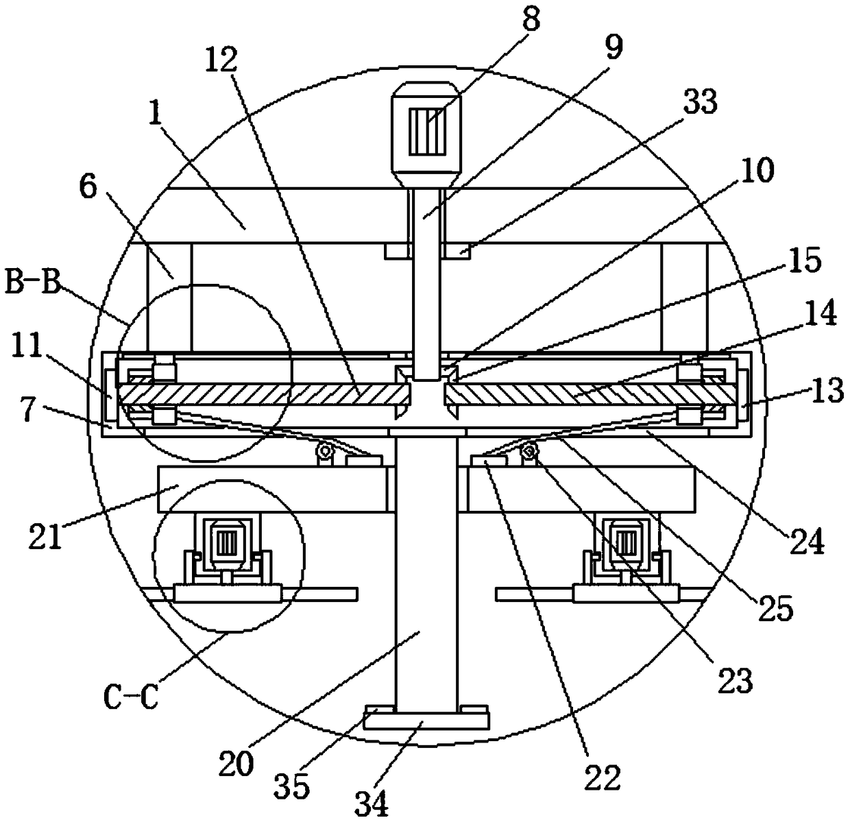
[0020] First implementation: see Figure 1-5, an energy-saving tempering furnace, comprising a shell 1, the top of the left and right sides of the inner wall of the shell 1 is fixedly connected with the first heating rod body 2, the bottom of the inner wall of the shell 1 is fixedly connected with the second heating rod body 3, the shell The inner wall of the housing 1 is fixedly connected with a stabilizing plate 4 above the second heating rod main body 3, the top of the stabilizing plate 4 is provided with a through hole 5, and the left and right sides of the top of the inner wall of the housing 1 are fixedly connected with a supporting plate 6, two The bottom of the support plate 6 is fixedly connected through the fixed shell 7, and the midpoint of the top of the shell 1 is fixedly connected with the rotating motor 8, and the output shaft of the rotating motor 8 is fixedly connected with the rotating shaft 9, and the bottom of the rotating shaft 9 is from top to bottom It r...

no. 2 approach

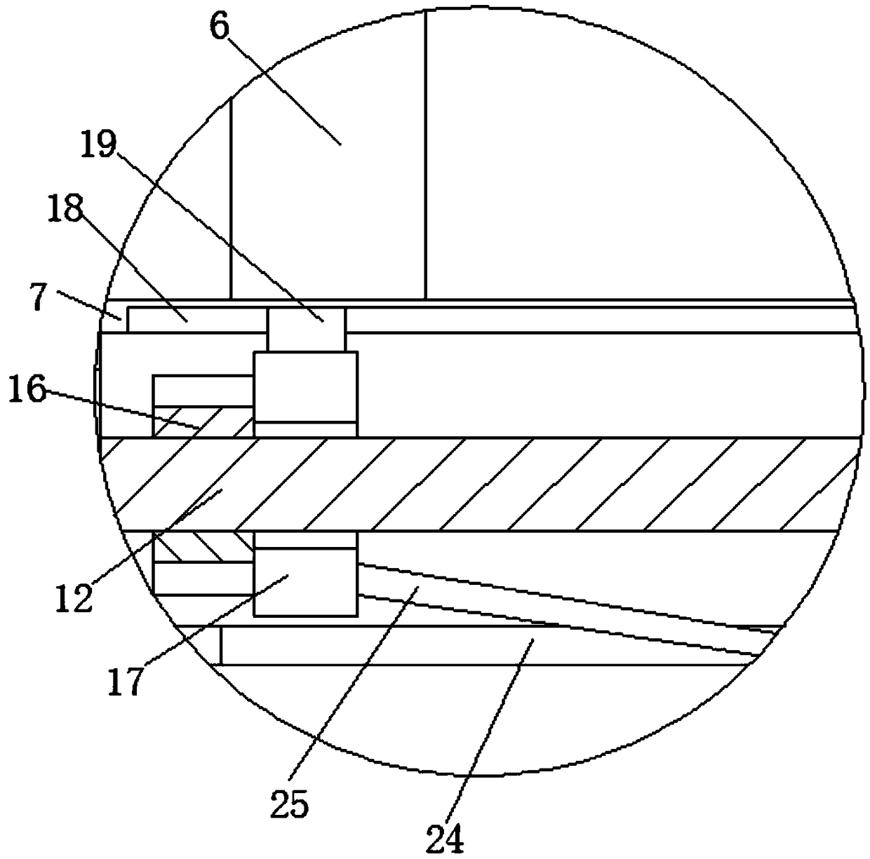
[0023] The second embodiment: as shown in claim 1, an energy-saving tempering furnace includes a shell 1, and the tops of the left and right sides of the inner wall of the shell 1 are respectively slidably supported and connected to a first heating rod body 2 through a chute, The chute has an initial damping, the bottom of the inner wall of the housing 1 is fixedly connected with the second heating rod main body 3, and the inner wall of the housing 1 is fixedly connected with a stabilizing plate 4 above the second heating rod main body 3, The stable plate has a double-layer structure, and the upper plate body and the lower plate body are supported by a plurality of densely arranged thermally expandable cylindrical materials, and through holes 5 with variable apertures are formed between the multiple cylinders. On the upper plate body A plurality of arc-shaped protrusions are also provided, and a plurality of cylinders close to the inner wall of the housing 1 are selected, and a...


PUM


Abstract

The invention discloses an energy-saving tempering furnace. The furnace comprises a casing, the top portions of left and right sides of an inner wall of the casing are fixedly connected with first heating rod bodies, the bottom of the inner wall of the casing is fixedly connected with a second heating rod body, and a stabilizer plate is fixedly connected to the inner wall of the casing and above the second heating rod body. Through the mutual cooperation of a rotating electric machine, a rotating shaft, a driving gear, a first rolling bearing, a forward rotating threaded rod, a second rollingbearing, a reverse threaded rod, a driven gear, a thread block, a movable block, a sliding groove, a sliding block, a sliding rod, a sliding plate, a counterweight, a pulley, a through groove, a steelwire rope, a stable motor, a stable rotating shaft, a fixed sleeve and fan blades, the furnace achieves the effect of high heating efficiency, solves the problem of low heating efficiency of the energy-saving tempering furnace, makes air circulate inside a tempering furnace body, greatly improves the work efficiency, reduces the time and effort of workers, and brings great convenience to a user.

Description

technical field [0001] The invention relates to the technical field of tempering furnaces, in particular to an energy-saving tempering furnace. Background technique [0002] With the continuous development of my country's industrial process, the industrial equipment required for industrial development is also constantly improving and developing. As an important pillar of industrial development, heat treatment technology has made great progress and development. Tempering is very important as a heat treatment process. Generally, a tempering furnace is needed to complete the tempering process. The tempering furnace is used for tempering general metal parts in the air and quenching, annealing and aging heat treatment for aluminum alloy die-casting parts, pistons, aluminum plates and other light alloy parts. , the heating efficiency of the common energy-saving tempering furnace is low, and the air inside the tempering furnace body does not circulate, resulting in uneven heating, wh...

Claims


Application Information

Patent Timeline
Patent Type & Authority Applications(China)
IPC IPC(8): C21D9/00C21D1/18
CPCC21D1/18C21D9/00
Inventor 高青
Owner 江苏富捷刀业有限公司
Why Eureka
Try Eureka