
Automatic dismounting type power battery box system

A power battery, automatic disassembly and assembly technology, applied in the field of new energy vehicles and energy storage power stations, can solve problems such as inability to control accidents in a timely and effective manner, inability to quickly isolate fault sources, and low degree of automation, so as to avoid further expansion of accidents, The effect of improving safety and reliability and eliminating potential safety hazards

Pending Publication Date: 2019-03-01
BIT HUACHUANG ELECTRIC VEHICLE TECH
View PDF0 Cites 6 Cited by
  • Summary
  • Abstract
  • Description
  • Claims
  • Application Information

AI Technical Summary

Problems solved by technology

[0003] At present, the installation and disassembly of the battery box is basically pushed or pulled out by manpower, and the screw fastening or manual pin is used for fixing, which is laborious and extremely low in production efficiency.
When a safety failure occurs in the battery, it is inconvenient to approach, the source of the failure cannot be quickly isolated, and the accident cannot be controlled in a timely and effective manner
[0004] The Chinese patent discloses a high-safety quick-change battery box locking device, which includes a battery box slide rail with a positioning hole and a locking hole at the end, a positioning pin, a positioning pin housing, and an early warning spring; the positioning pin Including the inner end of the positioning pin housing that is matched with the positioning hole and the locking hole respectively, the positioning pin housing is fixedly connected with the battery box slide rail, its structure is simple, and the degree of automation is low

Method used


Image

  • Automatic dismounting type power battery box system
  • Automatic dismounting type power battery box system
  • Automatic dismounting type power battery box system

Examples


Embodiment 1

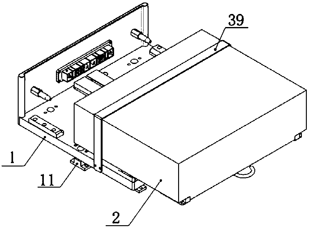
[0044] In this example, if figure 1 As shown, an automatic disassembly and assembly power battery box system includes a base 1 and a battery box 2 .

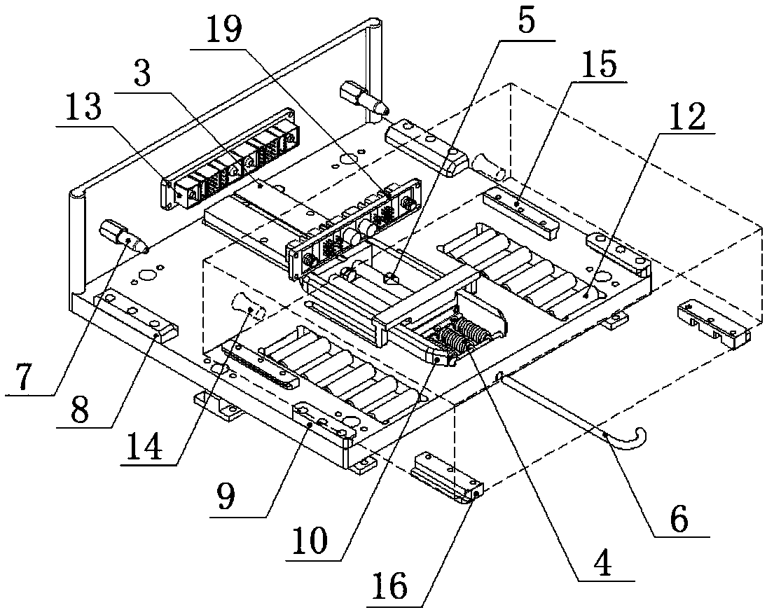
[0045] In this example, if figure 2As shown, the separation device 4, the locking device 5, the unlocking device 6, the positioning pin 7, the base primary guide rail (10), the secondary guide rail (8, 9), the base elastic member 11, the roller 12 and the connection are installed on the base 1. Device socket 13, its effect is to carry battery box 2. The battery box 2 is provided with positioning pin holes 14 , battery box guide rails ( 15 , 16 ), guide grooves 17 , power triggers 18 and connector plugs 19 .

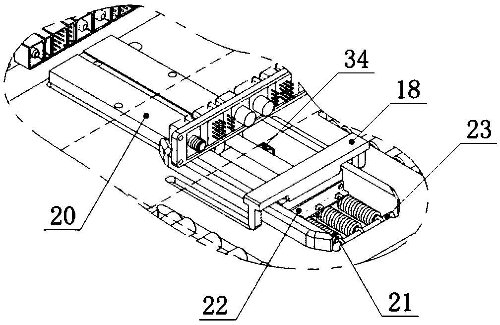
[0046] In this embodiment, the receiving device 3 includes a vehicle-mounted power source 20 and a power trigger 18. The vehicle-mounted power source 20 adopts an electric drive device, and the automatic storage and separation of the battery box 2 is realized through the electric drive device.

[0047] In this embodimen...

Embodiment 2

[0060] In this embodiment, an automatically disassembled power battery box system includes a base 1 and a battery box 2 .

[0061] In this embodiment, the base 1 is used to install the separation device 4, the locking device 5, the unlocking device 6, the positioning pin 7, the primary guide rails (8, 9) of the base, the secondary guide rails 10 of the base, the elastic parts 11 of the base, and the rollers 12 and connector socket 13, the battery case 2 is provided with the positioning pin hole 14 that cooperates with the positioning pin of the base 1, the guide groove 17 that cooperates with the primary guide rail of the base, and the guide rail (15, 9) that cooperates with the secondary guide rail (8, 9). 16), a power trigger 18 and a connector plug 19 matched with the connector socket 13.

[0062] In this embodiment, the absorbing device 3 includes a vehicle-mounted power source 20 and a power trigger 18, the vehicle-mounted power source 20 adopts a pneumatic cylinder, and ...


PUM


Abstract

The invention relates to an automatic dismounting type power battery box system. The automatic dismounting type power battery box system comprises a base and a battery box. The automatic dismounting type power battery box system adopts a vehicle-mounted power source to realize installation and separation of the battery box, and rapid guidance and graded positioning of the vehicle-mounted battery box; the uniformity of light and convenient guidance and accurate positioning is realized; the base and a vehicle body adopt a suspension mechanism connected with an elastic part; in an absorption process of the battery box, a lock tongue of a locking device is popped out under the action of a locking spring and the battery box is automatically locked; when the battery box has safety failures or isdismounted, an unlocking triggering device of an unlocking device is triggered, and the battery box and the base and a connector socket and a plug are rapidly separated through a separation spring; the battery box is smoothly released from the vehicle body and the safety hidden safety dangers hazards are eliminated; accidents are prevented from being further expanded.

Description

technical field [0001] The invention belongs to the technical field of new energy vehicles and energy storage power stations, and relates to an automatically disassembled power battery box system. Background technique [0002] At present, the environmental protection advantages of new energy vehicles such as energy saving, low noise, and zero emissions have the tendency to gradually replace traditional fuel vehicles, the development and utilization of clean new energy such as solar energy and wind energy, the demand for all-weather energy supply and rapid compensation of unbalanced power, energy storage batteries With higher technical feasibility and economic value, as the battery system of new energy vehicles and battery energy storage core components, quick disassembly and assembly can effectively solve the battery system's endurance, charging, installation, maintenance and other problems, especially when the battery system appears In the event of a safety failure, the bat...

Claims


Application Information

Patent Timeline
Patent Type & Authority Applications(China)
IPC IPC(8): H01M2/10B60K1/04H01M50/249
CPCB60K1/04B60K2001/0455H01M50/20Y02E60/10
Inventor 林程周辉时军辉侯睿董爱道吕日新
Owner BIT HUACHUANG ELECTRIC VEHICLE TECH
Learn More