Electric vehicle battery temperature control system

An electric vehicle and battery temperature control technology, applied in the field of auto parts related systems, can solve the problems of battery life, capacity and safety reduction, and achieve the effect of ensuring normal use and safety, ensuring capacity and safety, and increasing service life.

Pending Publication Date: 2019-03-01
程文君
View PDF0 Cites 0 Cited by
  • Summary
  • Abstract
  • Description
  • Claims
  • Application Information

AI Technical Summary

Problems solved by technology

[0003] Existing temperature control systems require an external power supply (generally low temperature) under high and low temperature conditions or use the power of power batteries in abnormal states to heat or dissipate the batteries to a suitable temperature. Generally, the working temperature range of lithium batteries used as power batteries is between 0℃~40℃, once the temperature exceeds this range, the battery life, capacity and safety will be reduced; therefore, the market urgently needs to develop a battery temperature control system for electric vehicles to help people solve existing problems

Method used


Image

  • Electric vehicle battery temperature control system
  • Electric vehicle battery temperature control system
  • Electric vehicle battery temperature control system

Examples


Embodiment 1

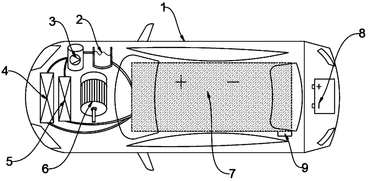
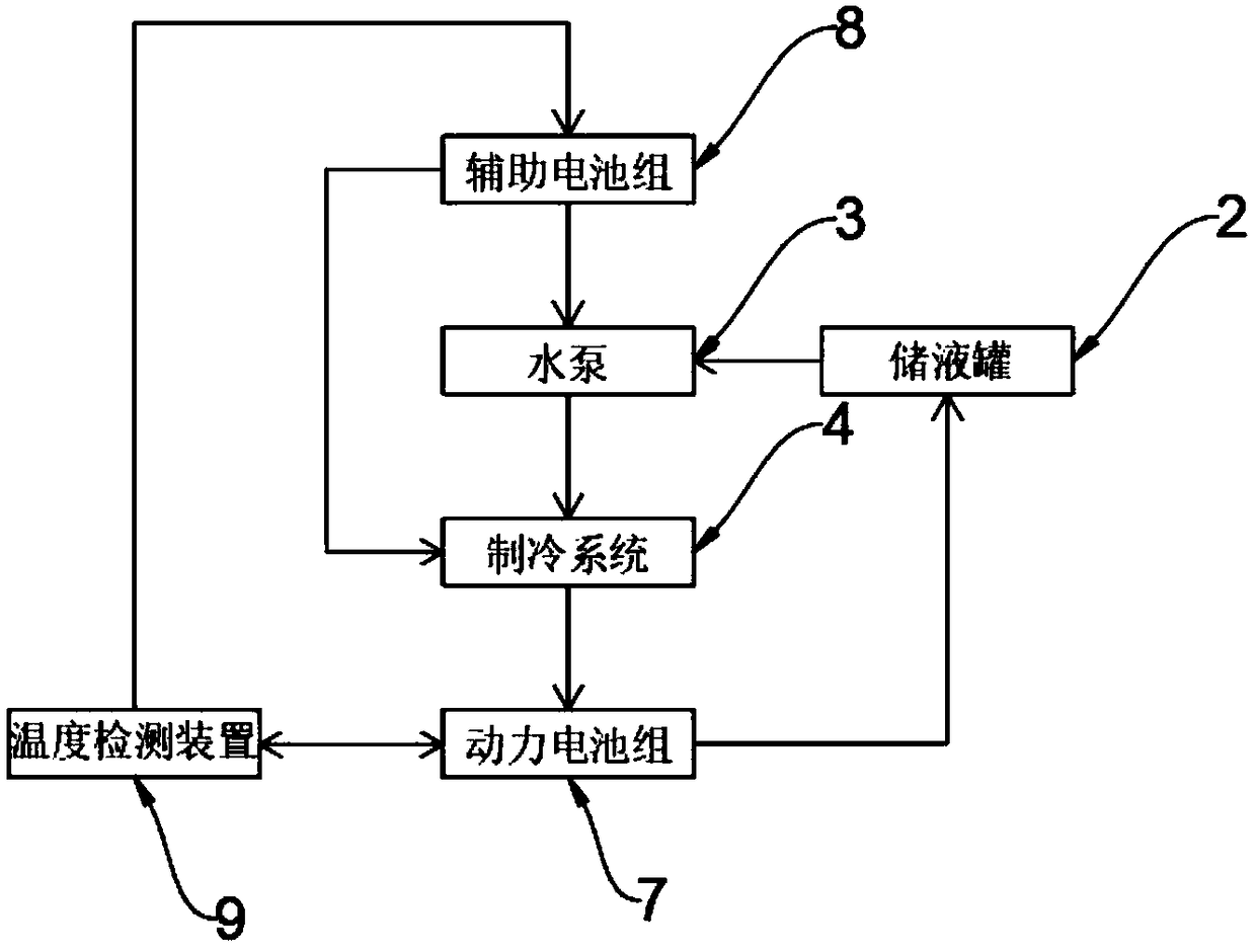
[0033] see figure 1 , figure 2 , an embodiment provided by the present invention: an electric vehicle battery temperature control system, including an electric vehicle 1, an auxiliary battery pack 8 is installed on one side of the electric vehicle 1, and a power battery is installed on the other side of the auxiliary battery pack 8 Group 7, a temperature detection device 9 is installed on one side of the lower end of the power battery pack 7, a motor 6 is installed on the other side of the power battery pack 7, a liquid storage tank 2 is installed on the upper end of the motor 6, and the other side of the liquid storage tank 2 A water pump 3 is installed, and the water pump 3 pumps out the antifreeze coolant from the liquid storage tank 2, and a heating system 5 is installed on the other side of the motor 6, and the heating system 5 is heated in advance to restore the working temperature range of the power battery pack 7 Normal value, the refrigeration system 4 is installed ...

Embodiment 2

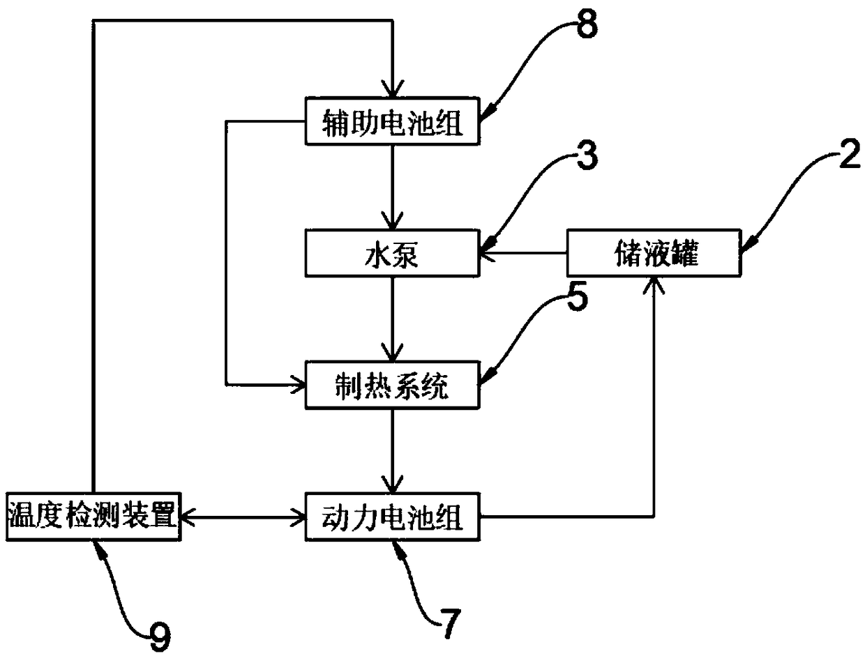
[0048] see figure 1 , image 3 , another embodiment provided by the present invention: an electric vehicle battery temperature control system, including an electric vehicle 1, an auxiliary battery pack 8 is installed on one side of the electric vehicle 1, and a power supply is installed on the other side of the auxiliary battery pack 8. A battery pack 7, a temperature detection device 9 is installed on one side of the lower end of the power battery pack 7, a motor 6 is installed on the other side of the power battery pack 7, a liquid storage tank 2 is installed on the upper end of the motor 6, and the other side of the liquid storage tank 2 A water pump 3 is installed on one side, and the water pump 3 pumps out the antifreeze coolant from the liquid storage tank 2. A heating system 5 is installed on the other side of the motor 6. The heating system 5 is heated in advance to make the working temperature range of the power battery pack 7 To return to the normal value, a refrige...


PUM


Abstract

The invention discloses an electric vehicle battery temperature control system, relates to the field of automotive parts related systems, and is intended to solve the problem that as working temperature of a lithium battery of a power battery pack in the prior art exceeds a working temperature range, battery life may be shortened, battery capacity may be decreased and battery safety may be lowered. An auxiliary battery pack is mounted on one side of the inside of an electric vehicle; a power battery pack is mounted on the other side of the auxiliary battery pack; a temperature detection deviceis mounted on one side of the lower end of the power battery pack; a motor is mounted on the other side of the power battery pack; a liquid storage tank is mounted at the upper end of the motor; a heating system is mounted on the other side of the motor; a cooling system is mounted on the other side of the heating system; an anti-freezing coolant pipe is arranged between the liquid storage tank and the water pump; an anti-freezing coolant pipe is arranged between the liquid storage tank and the power battery pack; an anti-freezing coolant pipe is also arranged between the water pump and the heating system.

Description

technical field [0001] The invention relates to the field of systems related to auto parts, in particular to an electric vehicle battery temperature control system. Background technique [0002] With the aggravation of problems such as environmental pollution and energy shortage, electric vehicles are developing extremely rapidly. At present, electric vehicles are divided into pure electric vehicles and hybrid vehicles, and most energy vehicles use lithium-ion power batteries as the power source. There are two main forms of existing electric vehicle battery cooling systems: one is air cooling, which is low in cost but poor in heat dissipation efficiency, and is mainly used in models with small battery capacity. The second is liquid cooling, which uses the circulating flow of antifreeze coolant to take away heat. [0003] Existing temperature control systems require an external power supply (generally low temperature) under high and low temperature conditions or use the pow...

Claims


Application Information

Patent Timeline
IPC IPC(8): H01M10/613H01M10/615H01M10/625H01M10/635H01M10/6556H01M10/6567B60L58/26B60L58/27
CPCH01M10/613H01M10/615H01M10/625H01M10/635H01M10/6556H01M10/6567H01M2220/20Y02E60/10Y02T10/70
Inventor 程文君
Owner 程文君
Why Eureka
Try Eureka