Liquid cooling plate and optical fiber laser
A liquid-cooling plate and heat-dissipating substrate technology, applied in lasers, laser parts, laser parts and other directions, can solve the problems of complex manufacturing process, uneven heat dissipation, complex liquid-cooling plate manufacturing process, etc., and achieve uniform heat dissipation and manufacturing process. simple effect
- Summary
- Abstract
- Description
- Claims
- Application Information
AI Technical Summary
Problems solved by technology
Method used
Image

Examples
Embodiment 1
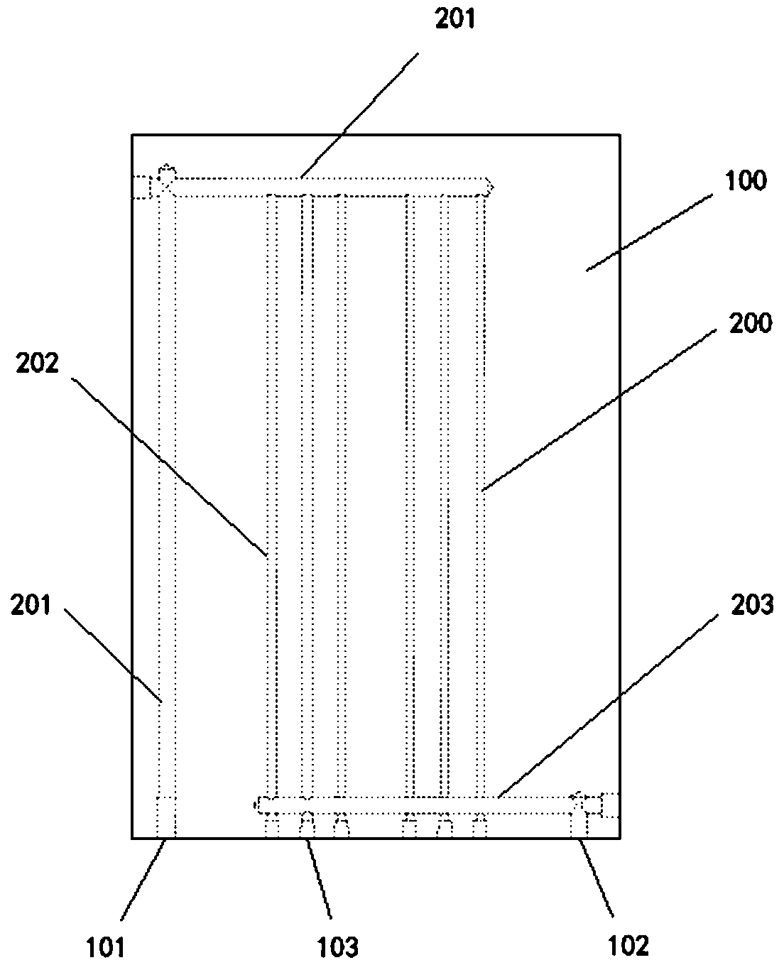
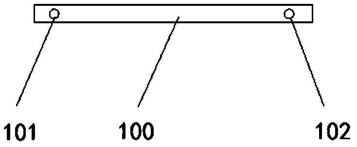
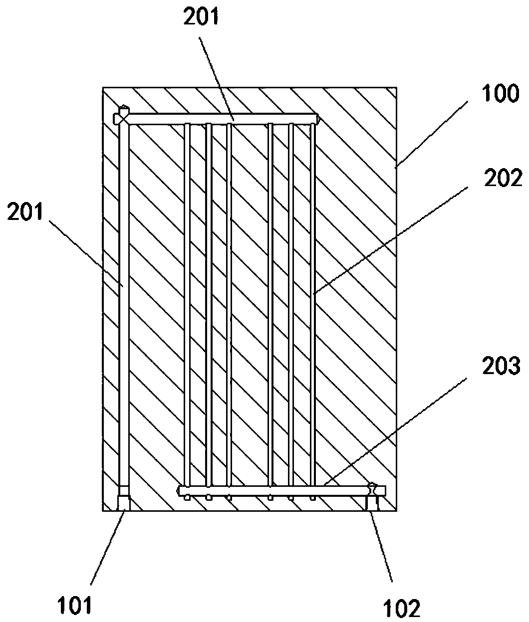
[0036] figure 1 A schematic diagram of the first structure of the liquid cold plate provided by the embodiment of the present invention from a first perspective; figure 2 A schematic diagram of the second perspective of the first structure of the liquid cold plate provided by the embodiment of the present invention; image 3 The cross-sectional view of the liquid channel in the first structure of the liquid cold plate provided by the embodiment of the present invention.
[0037] like Figure 1 to Figure 3 As shown, a liquid cold plate is provided in this embodiment, the liquid cold plate includes a heat dissipation substrate 100, and a liquid flow channel 200 disposed inside the heat dissipation substrate 100;
[0038] The liquid channel 200 includes at least two main channels and a plurality of sub-channels 202; both ends of the plurality of sub-channels 202 are respectively communicated with at least two of the main channels;
[0039] The heat dissipation substrate 100 i...
Embodiment 2
[0061] Figure 4 It is a schematic diagram of the second structure of the liquid cold plate provided by the embodiment of the present invention. like Figure 4 As shown, the liquid cold plate provided in this embodiment is a further improvement on the liquid cold plate provided in the first embodiment, and the technical solution described in the first embodiment also belongs to this embodiment. The technical solution will not be described repeatedly.
[0062] Specifically, as Figure 4 As shown, a liquid cooling plate is provided in this embodiment, which differs from the structure in Embodiment 1 in that the cross-sectional area of the multiple flow channels 202 is rectangular, rectangular or other irregular shapes.
[0063] In this embodiment, the heat dissipation substrate 100 adopts the method of extrusion molding after mold opening, and all the runners 202 are formed synchronously with the heat dissipation substrate 100 when they are re-extruded, so the runners 202 d...
Embodiment 3
[0065] This embodiment provides a fiber laser, and the fiber laser includes the liquid cooling plate in Embodiment 1 or Embodiment 2.
[0066] Specifically, in the liquid-cooled plate in this embodiment, the cross-sectional area of the main channel is larger than that of the branch channel, and the main channel includes the water inlet main channel 201 and the water outlet main channel 203 . The components with serious heat generation in the optical laser are installed on the main water inlet channel 201 or the main water outlet channel 203, and the components with low heat generation are installed on the shunt channel 202. The size of is correspondingly set above the shunt channel 202 with different cross-sectional areas. The fiber laser provided in this embodiment adopts the liquid-cooled plate provided in Embodiment 1 or Embodiment 2. The liquid-cooled plate can be designed in a differentiated manner according to the heat generated by the internal heating components. The ...
PUM
 Abstract
Description
Claims
Application Information
 - R&D
- Intellectual Property
- Life Sciences
- Materials
- Tech Scout
- Unparalleled Data Quality
- Higher Quality Content
- 60% Fewer Hallucinations
Browse by: Latest US Patents, China's latest patents, Technical Efficacy Thesaurus, Application Domain, Technology Topic, Popular Technical Reports.
© 2025 PatSnap. All rights reserved.Legal|Privacy policy|Modern Slavery Act Transparency Statement|Sitemap|About US| Contact US: help@patsnap.com