Cutting insert and replaceable cutting edge rotary cutting tool

A technology of cutting inserts and inserts, applied in milling cutting inserts, manufacturing tools, milling cutters, etc., can solve the problems of uneven properties of the machined surface and uniform machining accuracy of the unmachined surface, and achieve the effect of uniform properties and excellent machining surface accuracy.

Active Publication Date: 2019-03-01
HITACHI TOOL ENG LTD
View PDF8 Cites 1 Cited by
  • Summary
  • Abstract
  • Description
  • Claims
  • Application Information

AI Technical Summary

Problems solved by technology

That is, depending on the machined part and shape of the workpiece, the properties of the machined surface after cutting are not uniform, and the machining accuracy of the entire machined surface cannot be made uniform in finishing machining, semi-finishing machining, etc.

Method used


Image

  • Cutting insert and replaceable cutting edge rotary cutting tool
  • Cutting insert and replaceable cutting edge rotary cutting tool
  • Cutting insert and replaceable cutting edge rotary cutting tool

Examples


Embodiment Construction

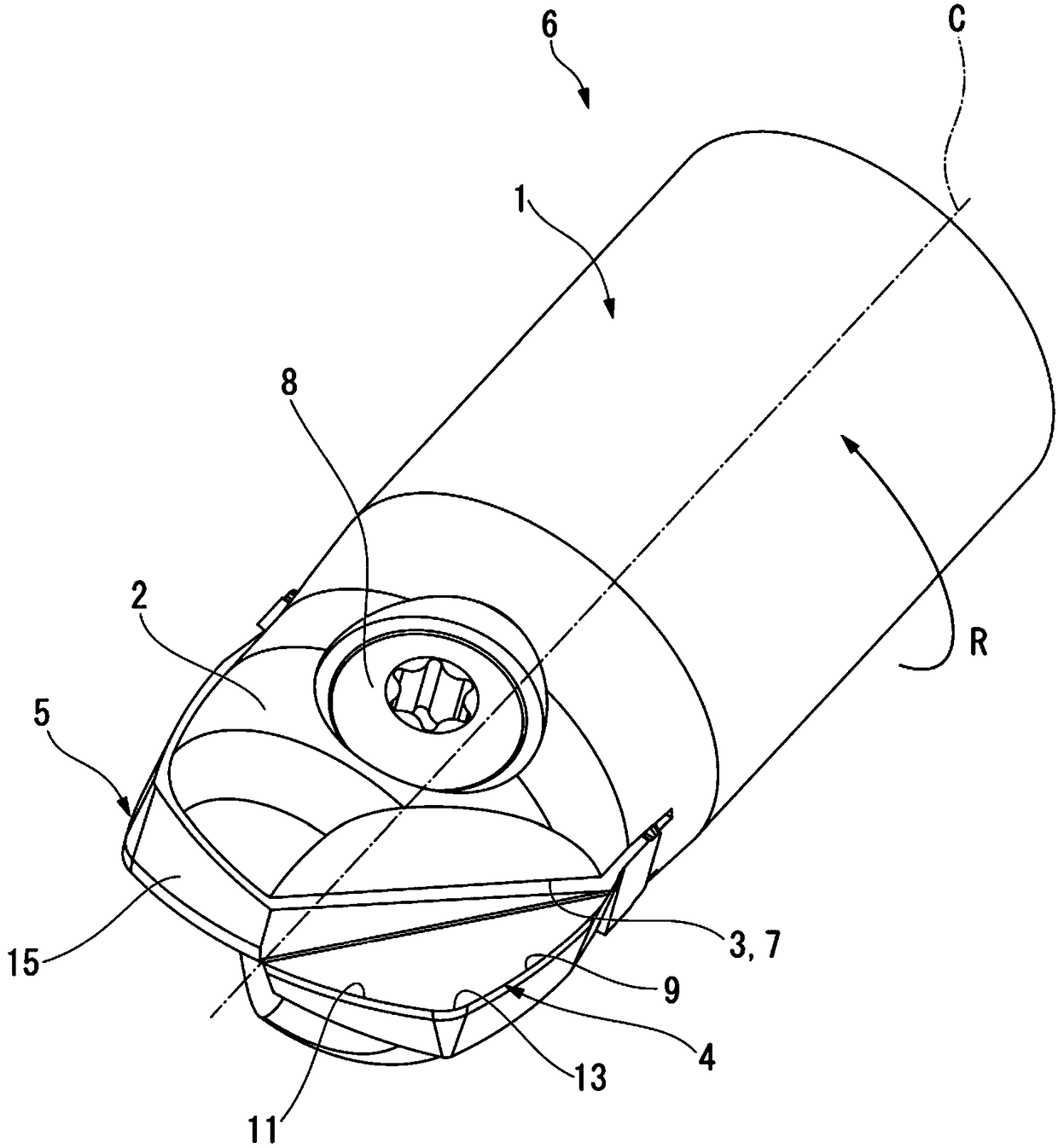
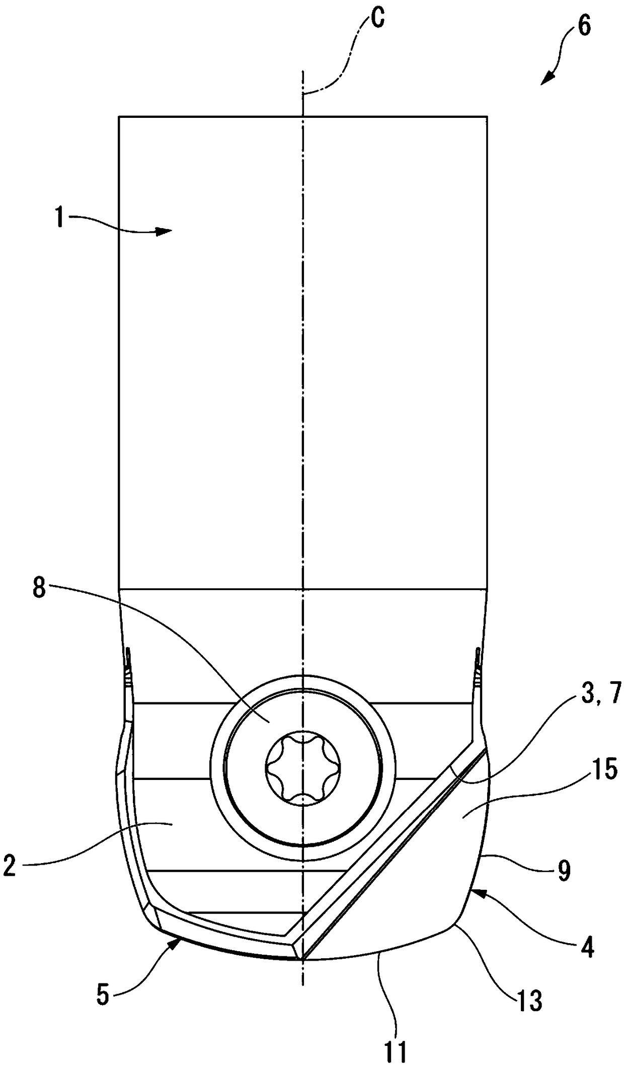
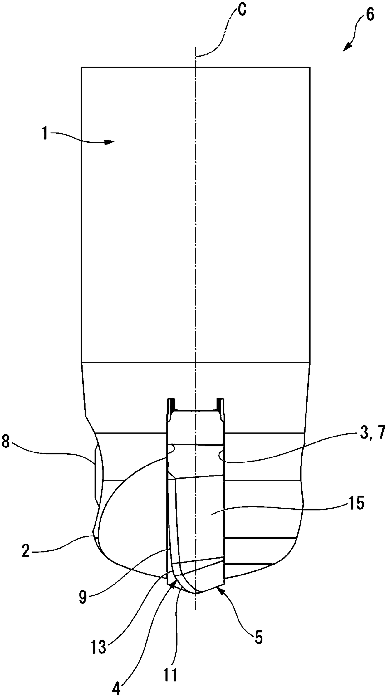
[0068] Next, a cutting insert 5 according to an embodiment of the present invention and an indexable insert type rotary cutting tool 6 including the cutting insert 5 will be described with reference to the drawings.

[0069] The cutting insert 5 of the present embodiment is a compound arc radius insert provided with a compound arc radius cutting edge, wherein the compound arc radius cutting edge consists of a so-called convex arc-shaped bottom cutting edge 11 called a lens, a so-called The outer peripheral cutting edge 9 of the convex arc shape of the drum and the convex arc radius cutting edge 13 of the cutting edge 13 connecting the bottom cutting edge 11 and the outer peripheral cutting edge 9 are constructed. Furthermore, the indexable insert type rotary cutting tool 6 having the cutting insert 5 is suitable for performing various cutting processes including end face cutting (surface machining) and side cutting (vertical wall surface machining) on ​​a workpiece, and can be ...


PUM


Abstract

This cutting insert (5) comprises a cutting edge portion (4). The cutting edge portion (4) comprises: an arc-shaped bottom cutting edge (11) that is convex to the distal end side in the direction of the central axis (C); an arc-shaped outer circumferential cutting edge (9) that is convex to the outside in the radial direction; and an arc-shaped corner-rounded cutting edge (13) that joins the outerend of the bottom cutting edge (11) in the radial direction and the distal end of the outer circumferential cutting edge (9) in the central axis (C) direction and that is convex to the distal outer circumferential side. The bottom cutting edge (11) and the outer circumferential cutting edge (9) are formed to be linearly symmetric to each other across a line of symmetry that is a virtual line (VL)passing through the center point of the arc (O) of the corner-rounded cutting edge (13) and intersecting the central axis (C) at a 45 degrees angle alpha.

Description

technical field [0001] The present invention relates to a cutting insert suitable for end face cutting (plane machining) or side cutting (vertical wall machining) of a workpiece, and an indexable insert type rotary cutting tool equipped with the cutting insert. [0002] This application claims priority based on Patent Application No. 2016-126975 filed in Japan on June 27, 2016, and uses the content thereof here. Background technique [0003] Conventionally, for example, solid end mills described in Patent Documents 1 and 2 below are known. This type of end mill includes a shank that rotates around a central axis, and a cutting edge formed at a tip portion of the shank. In addition, an arc-shaped bottom cutting edge protruding toward the front end side is arranged at the front end portion in the central axis direction of the cutting edge portion, and an arc-shaped outer periphery protruding radially outward is arranged at the radially outer end portion. Cutting edge. [00...

Claims


Application Information

Patent Timeline
Patent Type & Authority Applications(China)
IPC IPC(8): B23C5/20B23C5/10
CPCB23C5/20B23C5/10B23C5/109B23C2200/203B23C5/202B23C2200/28B23C2200/361
Inventor 小林由幸高桥勇人当麻昭次郎
Owner HITACHI TOOL ENG LTD
Why Eureka
Try Eureka