Refrigeration device for a power converter

A technology for power converters and cooling devices, used in indirect heat exchangers, cooling/ventilation/heating retrofits, electrical solid devices, etc., which can solve the complex installation of recirculation pumps, increase the possibility of failure, and reduce assembly reliability, etc. problems, to the effect of reducing the likelihood of failure and costly downtime, reducing the likelihood of leaks, and improving assembly reliability

Inactive Publication Date: 2019-03-01
ALAZ ARIMA SL
View PDF9 Cites 2 Cited by
  • Summary
  • Abstract
  • Description
  • Claims
  • Application Information

AI Technical Summary

Problems solved by technology

[0005] However, existing solutions have limitations
Sometimes the heat generated in a component is too much to use a heat sink of reasonable size
In addition, a recirculation pump is required to cool the components by means of a fluid, and the installation of the recirculation pump is very complicated and takes up a lot of space
Additionally, pipes often have various connections, increasing the possibility of leaks
All of these reduce assembly reliability and increase the likelihood of failure

Method used


Image

  • Refrigeration device for a power converter
  • Refrigeration device for a power converter

Examples


Embodiment Construction

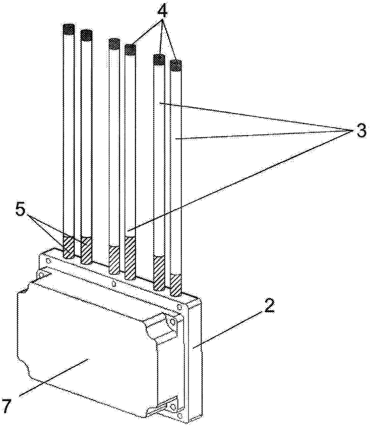
[0029] The object of the present invention is a device for discharging heat, replacing the mentioned hydraulic circuit with one or more preferably tubular conduits which will extend from the point of generation of heat to the point of discharge.

[0030] exist figure 1 In the shown embodiment of the invention, the power semiconductors (7) are coupled to a metal plate (2) into which a preferably tubular conduit (3) is inserted.

[0031] The conduit (3) can be fully inserted into the metal plate (2) or can be partially inserted, eg placed against one side of the metal plate (2).

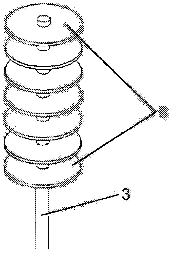
[0032] The fluid (5) performs a thermodynamic cycle based on phase change within the conduit (3). The lower part of the conduit (3), called the evaporator, receives the heat to be dissipated, and the fluid in liquid phase evaporates and turns into vapour. Due to the difference in density between the liquid and vapor states of all fluids, the vapor moves up to the higher and cooler part of the conduit...


PUM


Abstract

The invention relates to a refrigeration device for a power converter, comprising a plate (2) consisting of a thermally conductive material; and at least one conduit (3) containing a working fluid (5)selected for changing from a liquid phase to a gas phase and vice versa, during operation. The plate (2) has at least one housing for housing the conduit (3) where a first, lower portion of the conduit (3) is inserted into the plate (2), acting as an evaporator, and a second, upper portion of each conduit (3) remains outside the plate (2), acting as a condenser.

Description

technical field [0001] The invention pertains to cooling systems for cooling semiconductor-based power converters. Background technique [0002] Power converters are devices based on power semiconductors, usually IGBTs, whose purpose is to convert electrical energy between two different modes. Semiconductors generate heat during operation, and this heat must be dissipated to keep the semiconductor within its operating temperature range. [0003] Heat sinks coupled to components are known. A heat sink generally passively removes heat from the components it cools and rejects it to the outside air. To this end, the heat sink has a plate that is coupled to the semiconductor and contains fins to increase the contact surface with the air. The fins are usually made of aluminum due to its lighter weight, although the fins can also be made of copper due to its better thermal conductivity. In some applications, the cooling achieved by the heatsink is insufficient and requires the ...

Claims


Application Information

Patent Timeline
Patent Type & Authority Applications(China)
IPC IPC(8): F28D15/02H01L23/427H05K7/20
CPCF28D15/02H01L23/427H05K7/20F28D15/0241F28F1/30F28D15/0275F28D15/025H01L23/367H05K7/20327H05K7/20936
Inventor 郑烨J·J·阿瓜斯阿尔卡德L·乌尔塔多加西亚A·阿斯卡拉特安科纳
Owner ALAZ ARIMA SL
Why Eureka
Try Eureka