Grinding device for food processing machine

A technology for food processing machines and grinding devices, applied in applications, kitchen utensils, home utensils, etc., can solve the problems of inability to achieve filter-free slag-free, delicate taste, and motor shaft movement.

Active Publication Date: 2021-09-10
JOYOUNG CO LTD
View PDF0 Cites 0 Cited by
  • Summary
  • Abstract
  • Description
  • Claims
  • Application Information

AI Technical Summary

Problems solved by technology

However, due to the structural characteristics of the motor itself in the existing grinding food processing machines, the motor shaft will move axially during the operation of the motor. At the same time, due to the current manufacturing level and assembly accuracy, it cannot be accurately controlled. The grinding gap between the two grinding surfaces makes it impossible for the existing flat grinder food processor to produce a slurry drink that requires no filter, no slag, and a delicate taste.

Method used


Image

  • Grinding device for food processing machine
  • Grinding device for food processing machine
  • Grinding device for food processing machine

Examples


Embodiment 1

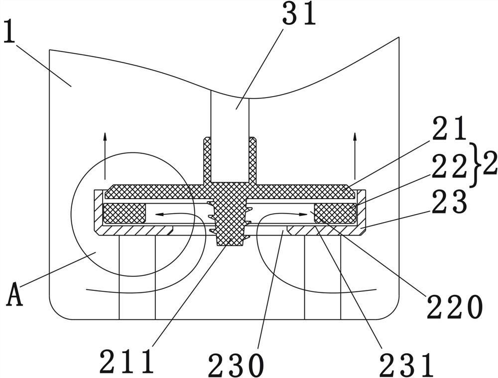
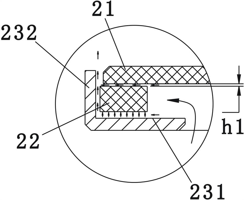
[0055] Such as figure 1 , figure 2 Shown is a schematic structural diagram of the first embodiment of the present invention. A food processing machine, comprising a cup body 1, a grinding device 2 is arranged in the cup body 1, and the grinding device 2 includes a rotating grinding disc 21 installed at the end of a rotating shaft 31 driven by a motor (not shown in the figure), Form a floating grinding disc 22 for plane grinding with the rotating grinding disc 21 and a support member 23 for supporting the floating grinding disc 22, the floating grinding disc 22 has a through hole 220 through the center, and the supporting member 23 has a supporting surface 231 for supporting the floating grinding disc 22 , and the edge of the supporting surface 231 is formed with a material passing opening 230 corresponding to the through hole 220, the rotating grinding disc 21 is located above the floating grinding disc 22, and when the rotating shaft 31 drives the rotating grinding disc 21 ...

Embodiment 2

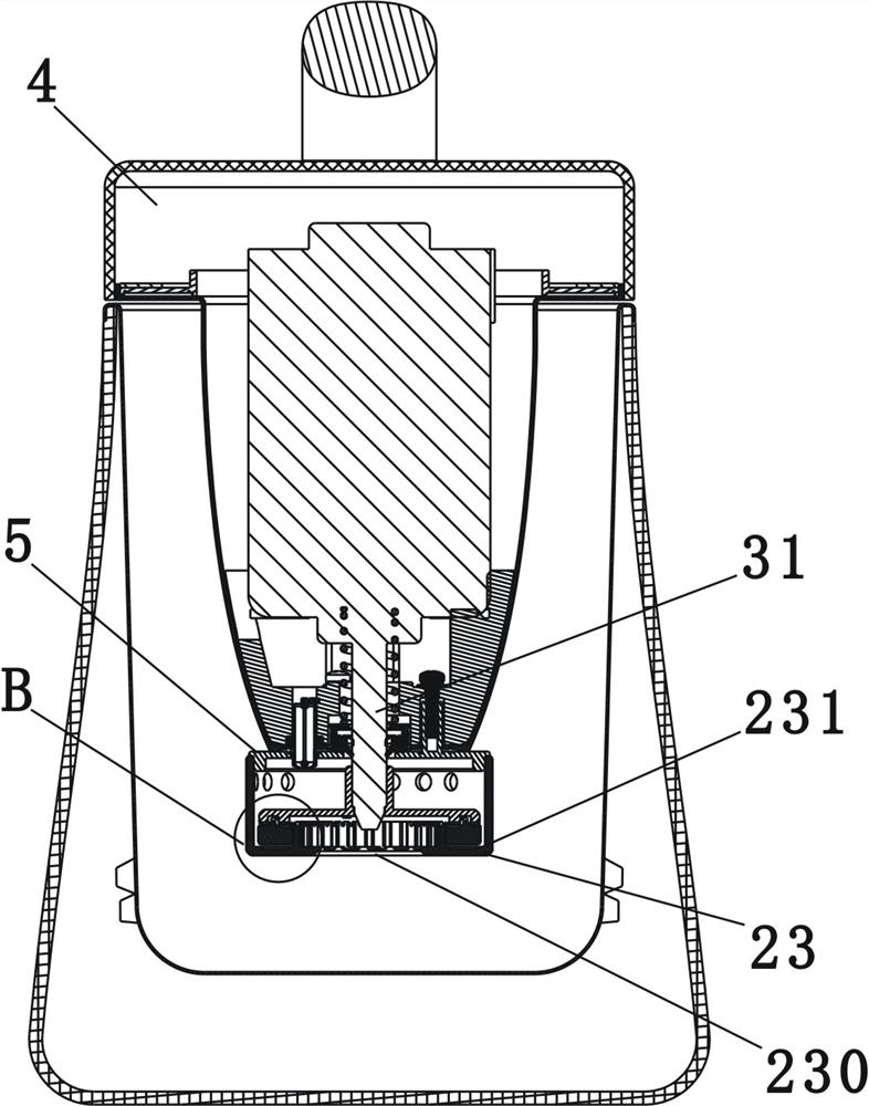
[0064] Such as Figure 3 to Figure 10 Shown is a schematic structural diagram of the second embodiment of the present invention. The difference between this embodiment and Embodiment 1 is that in this embodiment, the bottom of the machine head 4 is provided with a connecting piece 5, and the supporting piece 23 is a crushing cover screwed on the connecting piece 5, and the crushing cover has a barrel shaped peripheral wall 233, the barrel-shaped peripheral wall 233 is provided with a through hole 235, the rotating grinding disc 21 and the floating grinding disc 22 are located in the installation cavity formed by the barrel-shaped peripheral wall 233, and the supporting surface 231 is provided with an upward annular Protrusion 234, the annular protrusion 234 is arranged around the feeding opening 230, and the annular protrusion 234 extends into the through hole to radially limit the floating grinding disc 22, wherein the annular protrusion 234 is surrounded by the barrel-shaped...

Embodiment 3

[0073] Such as Figure 11 , Figure 12 , Figure 13 , Figure 14 Shown is a schematic structural view of the third embodiment of the present invention. The difference between this embodiment and Embodiment 2 is that in this embodiment, the support member is a guide tube 6, and the guide tube 6 is fixed on the bottom of the machine head by means of a screw clamp, and the surrounding wall of the guide tube 6 A discharge hole 60 is arranged on the top, and the bottom of the guide tube 6 shrinks to form an opening, and the material and liquid flow enter from the open end, and the guide tube 6 is located above the opening and is provided with a step surface 61 supporting the floating grinding disc 22, And the step surface 61 is provided with a positioning hole 610, and the bottom of the floating grinding disc 22 is provided with a positioning post 2210, and the positioning post 2210 cooperates with the positioning hole 610 to realize that the floating grinding disc 22 does not r...


PUM


Abstract

The invention relates to a small kitchen appliance, especially a grinding device for a food processor, which is characterized in that it includes a rotating grinding disc installed at the end of a rotating shaft, a floating grinding disc forming a plane grinding with the rotating grinding disc, and a support for supporting the floating grinding disc, The floating grinding disc has a through hole through the center, and the support member has a support portion supporting the floating grinding disc and a material passing opening corresponding to the through hole. The rotating grinding disc is located above the floating grinding disc, and the rotating shaft drives the rotating grinding disc to rotate. , the floating grinding disc floats in the axial direction between the rotating grinding disc and the supporting part. With the technical solution of the present invention, during the pulping process, the gap between the rotating grinding disc and the floating grinding disc can be adjusted adaptively, which not only improves the grinding and crushing efficiency of materials, but also greatly reduces the load on the motor and reduces the pulping noise , Cleaning is also more convenient.

Description

technical field [0001] The invention relates to a small kitchen appliance and its accessories, in particular to a grinding device for a food processing machine. Background technique [0002] Existing soya-bean milk machine, generally be provided with the crushing blade driven by rotating shaft in cup body, drive rotating shaft to rotate by motor and drive crushing blade to cut soybean material. For the soymilk machine of this crushing method, the structure is simple and the adaptability of the material is wide, but because the crushing blade is too sharp, it is easy to cut consumers during cleaning, and in the pulping process, the gap between the crushing blade and the soybean material The impact sound is loud, which affects the life and experience of consumers. [0003] At the same time, the food processor with low-speed surface grinding has low noise, does not hurt hands when cleaning, and the prepared slurry drink is closer to the original stone-ground soybean milk, whic...

Claims


Application Information

Patent Timeline
Patent Type & Authority Patents(China)
IPC IPC(8): A47J43/044A47J43/07
CPCA47J43/044A47J43/0711
Inventor 王旭宁于创江刘敦国
Owner JOYOUNG CO LTD
Why Eureka
Try Eureka