
Endoscope having a rotatable electric connecting element

A technology for connecting components and endoscopes, applied in the field of endoscopes, can solve the problems of contact wear and interference, achieve stable shape and achieve repeatable results

Active Publication Date: 2019-03-05
SCHOLLY FIBEROPTIC
View PDF5 Cites 1 Cited by
  • Summary
  • Abstract
  • Description
  • Claims
  • Application Information

AI Technical Summary

Problems solved by technology

However such contacts are subject to wear and are susceptible to interference

Method used


Image

  • Endoscope having a rotatable electric connecting element
  • Endoscope having a rotatable electric connecting element
  • Endoscope having a rotatable electric connecting element

Examples


Embodiment Construction

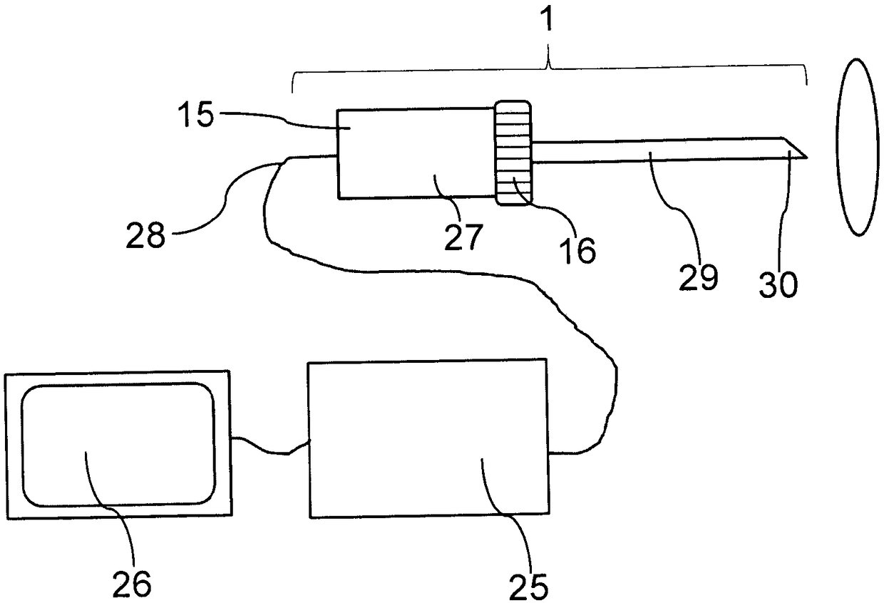
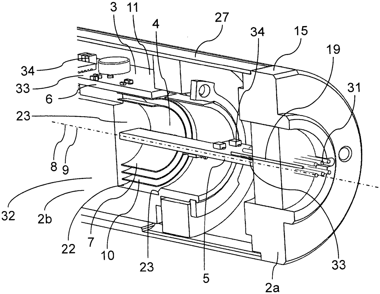
[0056] figure 1 An endoscope indicated by 1 as a whole is shown, which includes a handle 27, a rotating wheel 16 and an endoscope shaft 29. The image sensor is in the tip 30 of the endoscope, and the image sensor is figure 2 The cooling body indicated by 23 is connected. The cooling body 32 is rotatably supported with respect to the endoscope housing 15. By coupling the rotating wheel 16 with the cooling body 32 inside the endoscope 1, the image sensor can be rotated relative to the housing 15 and the endoscope rod 29 rigidly connected thereto. The rotating wheel 16 and the heat sink 32 thus form an external or internal coupling element.

[0057] In addition, the imaging optical system is located in the endoscope tip 30, and the optical system itself is connected to the endoscope shaft 29 and thereby the housing 15 so as not to rotate relative to one another. With the help of the camera cable 28, the video signal is transmitted from the image sensor of the endoscope 1 to the c...


PUM


Abstract

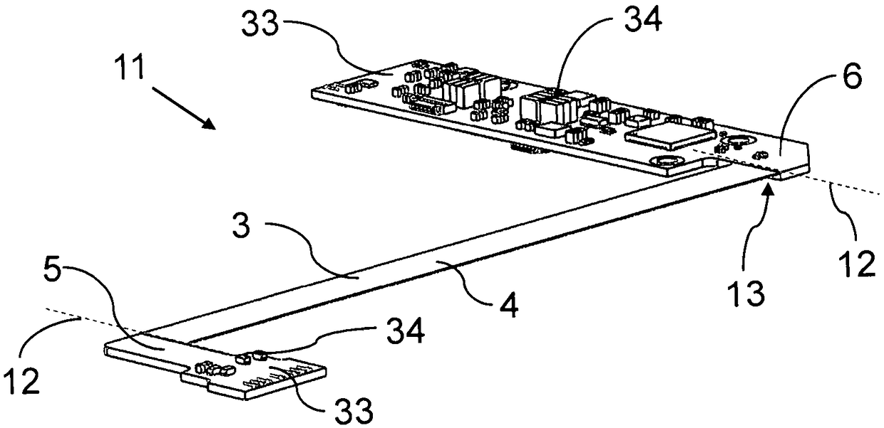
The invention relates to an endoscope comprising a rotatable electrical connecting element. A high-frequency transmission of data between functional units(2a,2b), which are mounted rotatably with respect to each other, of an endoscope(1), is permitted in which the functional units(2a,2b) can be electrically insulated from each other. For this, an electric connecting element which, in a central flexible portion, is rolled up transversely with respect to the direction of transmission and is fastened by its respective end portions to the functional units is provided. An uninterrupted electrical connection with consistent quality of the signal transmission can therefore be obtained even when the functional units are rotated in relation to each other. By the rolling up of the central portion(4)to form a winding(7), which is preferably configured in a self-supporting manner, a long term stable rotary degree of freedom is created in a very simple manner for the connecting element(3), with this degree of freedom permitting complex mechanical adjustment functions in the endoscope(1).

Description

Technical field [0001] The present invention relates to an endoscope, which comprises two functional units that are rotatable relative to each other and an electrical connection element, through which the two functional units are electrically connected or electrically connected to each other. Background technique [0002] In order to give video endoscope functions, such as mechanical zoom or focus adjustment or mechanical image horizontal orientation, for example, certain components of the endoscope must be rotatably supported. If these components also have or contact electrical connection devices or circuit boards, the corresponding electronic connections must also be ensured between the components or functional units that are rotatable relative to each other. The challenge here is to provide an electrical connection element that allows the functional units electrically connected to each other by means of the connection portion to rotate as resistance-free as possible without af...

Claims


Application Information

Patent Timeline
Patent Type & Authority Applications(China)
IPC IPC(8): A61B1/00A61B1/045
CPCA61B1/00098A61B1/00133A61B1/045H01R2201/12A61B1/00066A61B1/00179A61B1/00183A61B1/05H01R35/025H04N23/555H04N23/51H04N23/54H05K1/0278H05K1/189H05K5/06H05K2201/10121H05K2201/10151
Inventor M·库伯恩J·威克西姆J·迪特里希P·施普林M·齐肖茨
Owner SCHOLLY FIBEROPTIC
Learn More