Slag pot hauling special vehicle provided with slag pot automatic tipping mechanism

A technology of tipping mechanism and slag tank is applied in the field of special vehicles for slag tank pulling, which can solve the problems of increasing the labor intensity of employees, increasing the turnover time of slag tanks, and having a large number of spare slag tanks, so as to reduce the number of spare slag tanks and reduce The effect of labor intensity, process cost and maintenance cost reduction

Inactive Publication Date: 2019-03-05
刘江
View PDF0 Cites 2 Cited by
  • Summary
  • Abstract
  • Description
  • Claims
  • Application Information

AI Technical Summary

Problems solved by technology

[0006] 1. After the slag tank full of steel slag is pulled to the slag treatment site by a special vehicle, a crane needs to be used to lift the slag tank and place it on the slag tank tipping mechanism, which increases the turnover time of the slag tank and requires a relatively large number of spare slag tanks many
[0007] 2. The tipping mechanism needs to manually pull out the safety locking pin of the tipping mechanism when the slag tank is tipped over. When the slag tank is in normal use, it needs to manually install the locking pin of the tipping mechanism, and the locking pin is prone to fall off during use, causing tipping The mechanism falls off, so there is a great potential safety hazard
[0008] 3. The preparation and use process of the slag tank is cumbersome, which increases the labor intensity of the workers
[0009] 4. It is necessary to set up a special person to operate the slag tank tipping process, and the production efficiency is low

Method used


Image

  • Slag pot hauling special vehicle provided with slag pot automatic tipping mechanism

Examples


Embodiment Construction

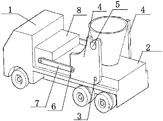
[0022] A special vehicle for hauling slag tanks with an automatic tipping mechanism for slag tanks, such as figure 1 As shown, there is a special vehicle 1 for hauling the slag tank, and an automatic tipping mechanism for the slag tank is installed on the frame of the special vehicle 1. Shafts 3 are respectively hinged with mutually symmetrical tilting brackets 4, and the tilting brackets 4 above the turning hinge shaft 3 are provided with a U-shaped trunnion seat matched with the trunnion 5 of the slag tank, which is located at the front of the turning hinge shaft 3 The connecting rod 7 is hinged on the tilting bracket 4 through the provided driving hinge shaft 6, and the other end of the connecting rod 7 is hinged with the hydraulic cylinder piston rod vertically arranged in the protective cover 8, wherein the driving hinge shaft 6 is at the bottom of the tilting bracket 4. The height of the side is greater than the height of the tipping hinge axis 3 from the tipping support...


PUM


Abstract

The invention belongs to a slag pot hauling special vehicle provided with a slag pot automatic tipping mechanism. The slag pot automatic tipping mechanism is installed on a frame of the special vehicle, according to the structure of the slag pot automatic tipping mechanism, tipping brackets symmetric mutually are separately hinged to overturning hinged shafts transversely arranged on the two sidesof a frame platform, a U-shaped trunnion seat matching with a slag pot trunnion is arranged on the tipping brackets located above the overturning hinged shafts, a connecting rod is hinged to the tipping brackets located on the front part of the overturning hinged shafts through a drive hinged shaft, the other end of the connecting rod is hinged to a hydraulic cylinder piston rod longitudinal arranged in a protective cover, and the height from the drive hinged shaft to the bottom edges of the tipping brackets is larger than the height from the tipping hinged shaft to the bottom edges of the tipping brackets. The structure is reasonable, the cycling time of a slag pot can be shortened, the number of spare slag pots used in site is reduced, the labor efficiency is improved, the process of fixing the tipping mechanism by bolts by workers before is removed, using is convenient, the labor strength of the workers is reduced, and safe operation of the workers is guaranteed.

Description

technical field [0001] The invention belongs to an auxiliary device for a slag tank tipping mechanism in a steelmaking plant, in particular to a slag tank pulling and transporting special vehicle with a slag tank automatic tipping mechanism. Background technique [0002] The slag tank is used to receive the steel slag after smelting qualified molten steel in the electric furnace or converter of the steelmaking plant, and then transport it to the slag treatment by special vehicles. [0003] After the slag tank is transported to the slag processing site by a special vehicle, the slag tank is hoisted by a crane, and then placed on the tipping mechanism. The tipping mechanism is operated to tip the slag tank, and the internal steel slag is poured out for processing. [0004] The slag tank is used to receive the steel slag after smelting qualified molten steel in the electric furnace or converter of the steelmaking plant, and then transport it to the slag treatment by special veh...

Claims


Application Information

Patent Timeline
Patent Type & Authority Applications(China)
IPC IPC(8): C21B3/10
CPCC21B3/10
Inventor 刘江
Owner 刘江
Why Eureka
Try Eureka