
Drainage pump and air conditioner

A technology of drainage pump and pump casing, applied in the direction of pumps, pump components, mechanical equipment, etc., to ensure quietness, ease impact, and reduce vibration

Active Publication Date: 2019-03-05
SAGINOMIYA SEISAKUSHO CO LTD
View PDF8 Cites 1 Cited by
  • Summary
  • Abstract
  • Description
  • Claims
  • Application Information

AI Technical Summary

Problems solved by technology

There is a problem that if the vibration propagates to the unit where the air conditioner drain pump is installed, the unit itself vibrates, causing noise

Method used


Image

  • Drainage pump and air conditioner
  • Drainage pump and air conditioner
  • Drainage pump and air conditioner

Examples


Embodiment Construction

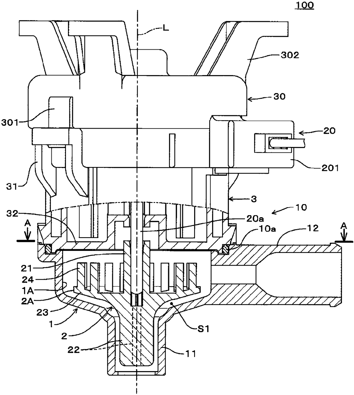
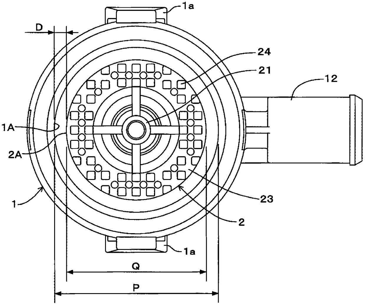
[0025] Next, embodiments of a drain pump according to the present invention will be described with reference to the drawings. figure 1 is a partially cutaway front view of the drainage pump of the embodiment, figure 2 This is the case after removing the cover figure 1 A-A direction view. In addition, the concept of "up and down" in the following description corresponds to figure 1 The top and bottom in the accompanying drawings.

[0026] The drain pump 100 of this embodiment includes a pump unit 10 , a motor unit 20 , and an upper cover 30 . The pump unit 10 has a resin cylindrical pump casing 1 , a resin pump rotor 2 described later, and a resin cylindrical cover 3 . Mounting arms 31 are formed on the outer periphery of the cover 3 . The motor unit 20 has a resin molded unit 201 that incorporates a circuit board and a stator and is integrally molded with resin. The upper cover 30 has a thin and circular lid shape, and a hook portion 301 is formed on the outer periph...


PUM

PropertyMeasurementUnit
Outer diameteraaaaaaaaaa
The inside diameter ofaaaaaaaaaa

Abstract

The invention provides a drainage pump and an air conditioner. In the drainage pump enabling a pump rotor (2) to rotate in a pump case (1), the vibration of the pump case (1) can be inhibited withoutreducing drainage flow. A centrifugal force is applied to the fluid in the pump case (1) by the pump rotor (2) inside the pump case (1). A gap (D) between the outer periphery of the pump rotor (2) andthe inner periphery of the pump case (1) is improved. The gap (D) is set that the outer diameter ratio (R) with respect to the outer diameter (Q) of the pump rotor (2) is above 8.5%. The outer diameter (Q) is set to be above 26mm and below 59.8mm, and the outer diameter ratio (R) is set to be above 8.5% and below 25%.

Description

technical field [0001] The present invention relates to, for example, a drain pump (drain pump) for draining drain water (condensation water) accumulated in a dew tray of an air conditioner, and an air conditioner including the drain pump. Background technique [0002] Conventionally, as a drain pump for an air conditioner, there is, for example, a device disclosed in JP-A-2017-106388 (Patent Document 1). In this type of drainage pump, a high flow rate is required as its performance, and in the device disclosed in JP-A-2017-106388, the shape of the projection (small vane) 12b of the shaft portion 12B of the pump rotor in the pump casing is improved. Increase the flow of drainage. [0003] prior art literature [0004] Patent Document 1: Japanese Patent Laid-Open No. 2017-106388 Contents of the invention [0005] The problem to be solved by the invention [0006] In the device of Patent Document 1, the flow rate can be increased, but when the lift is low, the drain pump...

Claims


Application Information

Patent Timeline
IPC IPC(8): F04D1/14F04D29/22F04D29/42F24F13/22
CPCF04D1/14F04D29/2216F04D29/426F24F13/222
Inventor 富田沙祈子渡边秀刚滨田正吾日下直树
Owner SAGINOMIYA SEISAKUSHO CO LTD
Features
  • Generate Ideas
  • Intellectual Property
  • Life Sciences
  • Materials
  • Tech Scout
  • Unparalleled Data Quality
  • Higher Quality Content
  • 60% Fewer Hallucinations
Learn More