
Tubular reactor for lithium flow battery

A tubular reactor and liquid flow battery technology, which is applied in the direction of fuel cells, fuel cell additives, regenerative fuel cells, etc., can solve the problem of not being able to fully utilize the high energy density of lithium flow battery electrode slurry and restricting grid energy storage systems Large-scale application, affecting the overall performance of lithium flow batteries and other issues, to achieve good space utilization and adaptability, improve the effective reaction area, and reduce the total amount of consumables

Active Publication Date: 2019-03-05
BEIJING HAWAGA POWER STORAGE TECH +1
View PDF5 Cites 0 Cited by
  • Summary
  • Abstract
  • Description
  • Claims
  • Application Information

AI Technical Summary

Problems solved by technology

The effective reaction area of ​​this type of battery reactor is relatively low, and it cannot give full play to the advantages of high energy density of lithium flow battery electrode paste
In order to achieve the designed output power, it is often necessary to increase the volume of the electrode slurry, which consumes additional materials such as battery casings, current collectors, and porous diaphragms, which increases battery manufacturing costs.
In addition, defects such as large flow resistance in conventional battery reactors affect the overall performance of lithium flow batteries and restrict their large-scale application in grid energy storage systems.

Method used


Image

  • Tubular reactor for lithium flow battery
  • Tubular reactor for lithium flow battery
  • Tubular reactor for lithium flow battery

Examples


Embodiment Construction

[0060] The present invention will be further described through embodiments below in conjunction with the accompanying drawings.

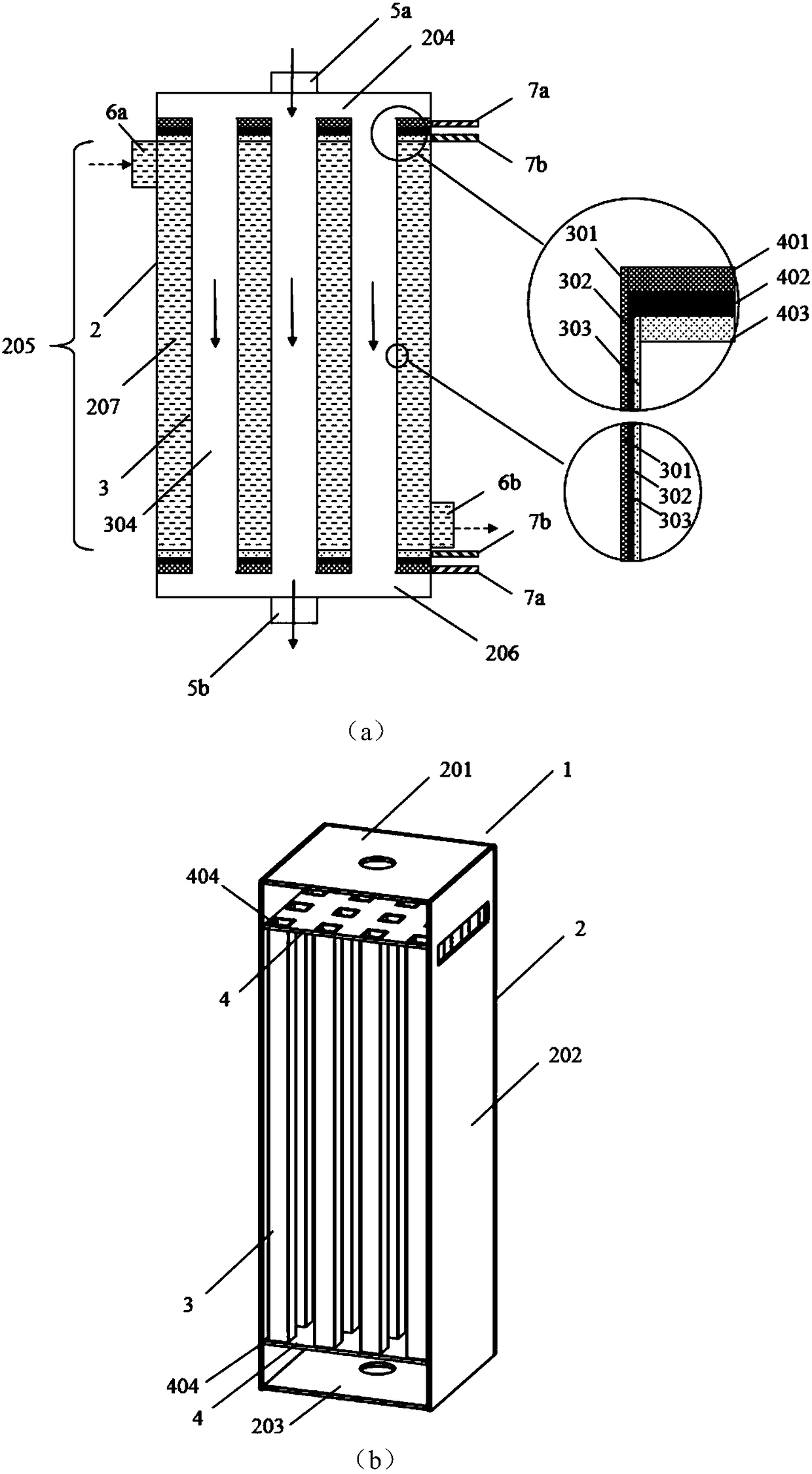
[0061] figure 1 is a schematic diagram of a tubular reactor according to the present invention, wherein, figure 1 (a) is the longitudinal section of tubular reactor and the schematic diagram of partial enlargement, figure 1 (b) is a three-dimensional schematic diagram of a tubular reactor. The tubular reactor 1 includes an outer tube 2, an inner tube 3, a composite collector plate 4, a first electrode slurry inlet 5a, a first electrode slurry outlet 5b, a second electrode slurry inlet 6a, and a second electrode slurry outlet 6b, the first tab 7a and the second tab 7b. The outer tube 2 includes a top 201 , a side wall 202 and a bottom 203 , the first electrode slurry inlet 5 a is set at the top 201 of the outer tube, and the first electrode slurry outlet 5 b is set at the bottom 203 of the outer tube. The upper part of the upper composite current...


PUM


Abstract

The invention provides a tubular reactor for a lithium flow battery. The tubular reactor comprises an outer tube and an inner tube arranged in the outer tube; a cavity is formed in the inner tube andis used for containing positive slurry or negative slurry; and a cavity is formed between the outer tube and the inner tube, and is used for containing negative slurry or positive slurry. The tube wall of the inner tube adopts a bipolar diaphragm, so that a space for containing the electrode slurry can be formed through the tube wall formed by the bipolar diaphragm, and an electrochemical reactionof the electrode slurry inside and outside of the inner tube can be realized. Compared with a traditional planar structure, the nested tubular structure can obtain a larger effective reaction area from a reactor of the same volume, so that the energy density is further increased. Moreover, the tubular structure is smoother than the flow passage of the planar structure, flowing of the electrode slurry is facilitated, and the driving energy consumption of the electrode slurry is reduced. In addition, the shapes and arrangement modes of the inner tube and the outer tube are flexible and changeable, so that the lithium flow battery has higher space utilization rate and adaptability.

Description

technical field [0001] The invention relates to the field of lithium flow batteries, in particular to a tubular reactor for lithium flow batteries. Background technique [0002] Lithium flow battery is a new type of electrochemical energy storage technology. Different from the solid electrode material of conventional lithium-ion batteries, the electrode material of lithium flow battery is a viscous non-aqueous electrode slurry composed of organic electrolyte, electrode active material and conductive agent. Drive, continuously or indirectly flow into the reactor for electrochemical reaction, so as to realize the storage or output of electric energy. Lithium flow batteries combine the high energy density of traditional lithium-ion batteries with the flexible expansion and long service life of flow batteries. The field has broad application prospects. [0003] High-efficiency battery reactors can provide good energy exchange efficiency for lithium flow batteries, so battery ...

Claims


Application Information

Patent Timeline
IPC IPC(8): H01M8/18
CPCH01M8/0258H01M8/0273H01M8/04276H01M8/188Y02E60/50
Inventor 谢晨陈永翀冯彩梅何颖源张彬王玉伟秦志健张艳萍
Owner BEIJING HAWAGA POWER STORAGE TECH
Learn More