Antenna part, vehicle-mounted radar and automobile

A component and antenna technology, applied in antenna components, antennas, resonant antennas, etc., can solve the problems of increasing the overall price of radar, high overall price of radar, and increasing the area of ​​millimeter-wave dielectric substrates, so as to achieve improved signal-to-noise ratio and large Beam range, effect of improving cost performance and competitiveness

Active Publication Date: 2019-03-05
BYD CO LTD
View PDF10 Cites 3 Cited by
  • Summary
  • Abstract
  • Description
  • Claims
  • Application Information

AI Technical Summary

Problems solved by technology

[0005] However, as we all know, the unit price of the millimeter-wave dielectric substrate is much higher than that of the low-frequency PCB (Printed Circuit Board, printed circuit board) dielectric substrate. The larger the area used by the millimeter-wave dielectric substrate, the higher the overall price of the radar.
Therefore, using the WR12 standard waveguide feed interface for the above-mentioned microstrip comb array antenna will result in the use of at least two millimeter-wave dielectric substrates, that is, the increase in the area of ​​the millimeter-wave dielectric substrate and the increase in the overall price of the radar, which cannot meet the increasingly competitive automotive millimeter-wave requirements. Price Demand in the Radar Market
Moreover, the above-mentioned microstrip comb array antenna needs to use a metal waveguide, a metal waveguide flange, or other metal structural parts containing a waveguide cavity to connect the above-mentioned MMIC dielectric substrate, resulting in the in-vehicle millimeter-wave radar The overall weight increases, which cannot meet the needs of lightweight vehicles

Method used


Image

  • Antenna part, vehicle-mounted radar and automobile
  • Antenna part, vehicle-mounted radar and automobile
  • Antenna part, vehicle-mounted radar and automobile

Examples


Embodiment Construction

[0043] Embodiments of the present invention are described in detail below, examples of which are shown in the drawings, wherein the same or similar reference numerals designate the same or similar elements or elements having the same or similar functions throughout. The embodiments described below by referring to the figures are exemplary and are intended to explain the present invention and should not be construed as limiting the present invention.

[0044] An antenna component, a vehicle radar and a car according to an embodiment of the present invention will be described below with reference to the accompanying drawings.

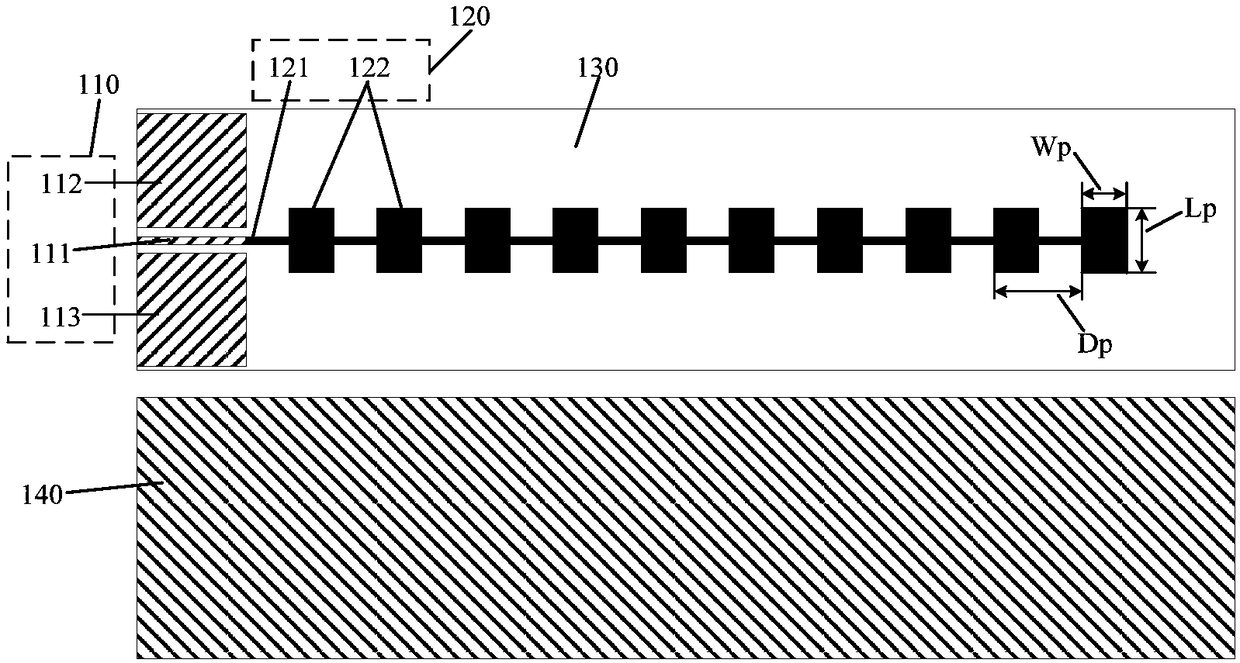
[0045] figure 1 A schematic structural diagram of an antenna component according to an embodiment of the present invention.

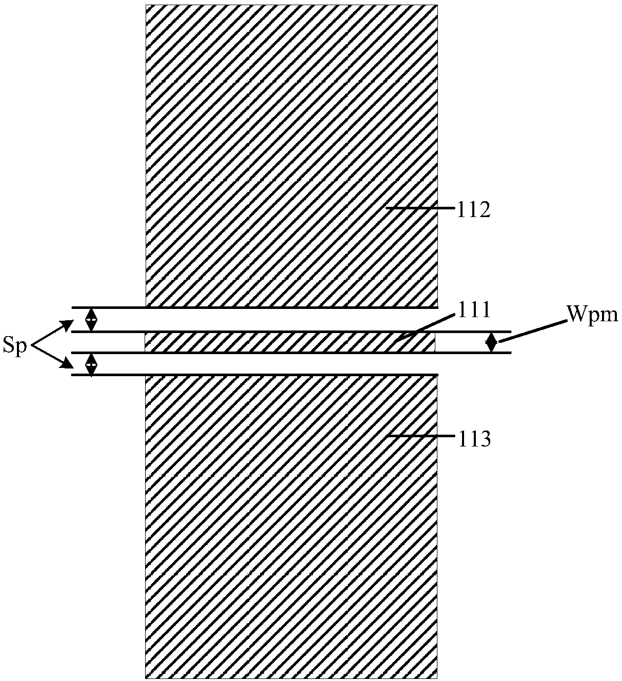
[0046] like figure 1 As shown, the antenna component may include: a dielectric substrate 130, a coplanar waveguide component 110 formed on one side of the dielectric substrate 130, an array antenna 120 formed on one side of the d...


PUM


Abstract

The invention discloses an antenna part, a vehicle-mounted radar and an automobile. The antenna part comprises a dielectric substrate, a coplanar waveguide assembly, an array antenna, a wave beam width adjustment assembly and a back grounding plate, wherein the coplanar waveguide assembly is formed at one side of the dielectric substrate, the array antenna is connected with the coplanar waveguideassembly, the array antenna comprises at least one microstrip feeding line and a plurality of array patches, the plurality of array patches are arranged on the microstrip feeding line and are dividedto two groups, the widths of the two groups of array patches are different, the wave beam width adjustment assembly is arranged in a circling the array antenna, and the back grounding plate is formedat the other side of the dielectric substrate and covers a part right below the coplanar waveguide assembly, the array antenna and the wave beam width adjustment assembly. The antenna part and an MMICare easily arranged on the same surface of the dielectric substrate, the application area of the dielectric substrate is favorably reduced, the integral cost of the vehicle-mounted radar is reduced,moreover, a metal structure member containing a waveguide cavity is not needed to be used, and the integral quality of the radar can be reduced.

Description

technical field [0001] The invention relates to the technical field of antennas, in particular to an antenna component, a vehicle-mounted radar with the antenna component and a vehicle with the vehicle-mounted radar. Background technique [0002] Due to the advantages of low profile and low cost, microstrip antennas are widely used in various vehicle radars. [0003] In the related technology, a microstrip comb array antenna applied in the 77GHz millimeter wave frequency band is proposed. The array antenna is mainly composed of a waveguide microstrip transition part, a comb radiation array antenna and a dielectric substrate. Among them, the waveguide microstrip transition part It is mainly composed of waveguide short-circuit surface, patch unit and WR12 standard waveguide feeding interface, and the patch unit and WR12 standard waveguide feeding interface are on the front of the dielectric substrate, and the comb radiation array antenna is on the back of the dielectric substr...

Claims


Application Information

Patent Timeline
Patent Type & Authority Applications(China)
IPC IPC(8): H01Q21/00H01Q1/38H01Q1/32H01Q1/48H01Q1/50H01Q9/04
CPCH01Q1/3233H01Q1/38H01Q1/48H01Q1/50H01Q9/045H01Q21/0006
Inventor 黄忠伟姜波
Owner BYD CO LTD
Why Eureka
Try Eureka