
Real-time high-resolution spatio-temporal distribution imaging method and system for focused ultrasonic cavitation

A technology focused on ultrasound and time-space distribution, applied in ultrasound/sound wave/infrasonic wave diagnosis, sound wave diagnosis, infrasonic wave diagnosis, etc., can solve the problem of lack of calculation method of space-time distribution of cavitation activity, interaction between microbubbles, array transducer defect array Aperture and bandwidth, poor spatial resolution, etc.

Active Publication Date: 2019-03-08
XI AN JIAOTONG UNIV
View PDF9 Cites 13 Cited by
  • Summary
  • Abstract
  • Description
  • Claims
  • Application Information

AI Technical Summary

Problems solved by technology

However, the existing passive acoustic imaging algorithms based on time-exposure acoustics have extremely poor spatial resolution performance due to factors such as microbubble interactions, array transducer defects, limited array aperture and bandwidth; at the same time, there is also a lack of effective The calculation method of the temporal and spatial distribution of cavitation activity cannot meet the clinical needs of a real-time monitoring system for focused ultrasound therapy

Method used


Image

  • Real-time high-resolution spatio-temporal distribution imaging method and system for focused ultrasonic cavitation
  • Real-time high-resolution spatio-temporal distribution imaging method and system for focused ultrasonic cavitation
  • Real-time high-resolution spatio-temporal distribution imaging method and system for focused ultrasonic cavitation

Examples


Embodiment Construction

[0079] The present invention will be further described in detail below in conjunction with the accompanying drawings and embodiments.

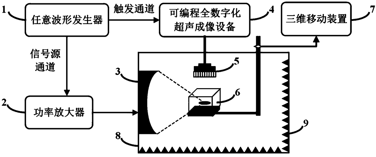
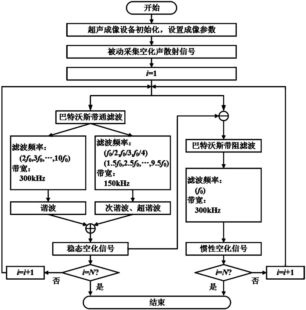
[0080] The present invention provides a real-time high-resolution temporal-spatial distribution imaging method of focused ultrasound cavitation based on passive acoustic imaging, which collects cavitation in the process of focused ultrasound by synchronously triggering focused ultrasound transducers and programmable full-digital ultrasound imaging equipment Acoustic scattering signals, and design filters to extract steady-state and inertial cavitation signals; improve the existing passive acoustic imaging method based on high-resolution coherence coefficients, effectively improve imaging spatial resolution, and obtain high-resolution steady-state and inertial cavitation signals Then, the steady-state and inertial cavitation time-series images are screened by measuring the focal area size of the focused ultrasonic transducer and the additional c...


PUM


Abstract

The invention provides a real-time high-resolution spatio-temporal distribution imaging method and system for focused ultrasonic cavitation. A cavitation acoustic scattering signal is filtered to obtain a steady state and an inertial cavitation signal; an existing passive acoustic imaging algorithm is modified based on a high-resolution coherence coefficient to obtain a high-resolution steady state and an inertial cavitation image; the cavitation image is screened, the additional cavitation energy is removed, the steady state and an inertial cavitation feature image are obtained through the principal component analysis, and on the basis, the spatio-temporal distribution of the steady state and the inertial cavitation is obtained. The method can solve the problems that active ultrasound imaging can only obtain cavitation microbubble distribution and cannot obtain the spatio-temporal distribution of a cavitation activity, and passive acoustic imaging is poor in resolution and lacks effective cavitation spatio-temporal distribution calculation methods, provide an effective means for cavitation transient physics process researches and focused ultrasound therapy evaluation, and lay thefoundation for the clinical application of ultrasound-guided and monitored focused ultrasound therapy systems.

Description

technical field [0001] The invention belongs to the field of ultrasonic cavitation physics and application and ultrasonic imaging technology, and specifically relates to a real-time high-resolution time-space distribution imaging method and system of focused ultrasonic cavitation. Background technique [0002] Cavitation refers to a series of dynamic processes in which cavitation nuclei in liquids oscillate, grow, shrink, and collapse under the action of external physical fields (such as ultrasonic fields, laser fields, etc.). , in vitro lithotripsy, drug release, hemostasis, thrombolysis and tumor thermal ablation and other fields are used. According to the different dynamic behaviors of bubbles, cavitation can be divided into two types: steady-state cavitation and inertial cavitation. Steady-state cavitation mainly refers to the nonlinear vibration behavior of microbubbles under the action of low sound pressure, while inertial Melting mainly refers to the instantaneous ru...

Claims


Application Information

Patent Timeline
IPC IPC(8): A61B8/00
Inventor 万明习路舒宽余先波李任晏
Owner XI AN JIAOTONG UNIV
Learn More