Rolling roller set system for rolling waste railway steel rail

A roll set and rail technology, which is applied in the field of rolling roll set system for rolling waste railway rails, can solve the problems of material waste, high energy consumption, and irregular edges of raw materials, etc.

Inactive Publication Date: 2019-03-08
临沂市兴华工程机械有限公司
View PDF0 Cites 4 Cited by
  • Summary
  • Abstract
  • Description
  • Claims
  • Application Information

AI Technical Summary

Problems solved by technology

However, the technology of using plasma cutting technology and other similar technologies to cut waste railway rails into three parts: rail top, rail waist, and rail bottom still relies heavily on manual operation, high energy consumption, and relatively large waste of materials. The raw material edge is not neat and the economic cutting cost is high.

Method used


Image

  • Rolling roller set system for rolling waste railway steel rail

Examples


Embodiment Construction

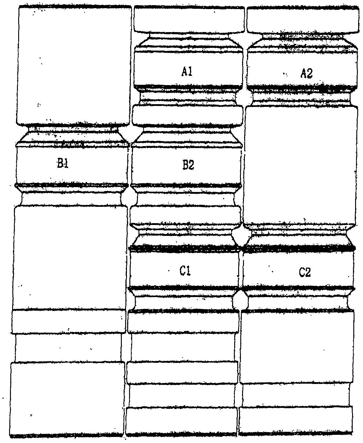
[0018] Such as figure 1 As shown, the rolling roll group system for rolling scrap railway rails of the present invention, the first rolling roll group A1A2 is a rolling roll group that expands grooves along the railway rail hole shape after being heated, and the second rolling roll group The rolling roll group B1B2 is the rolling roll group for indentation rolling along the boundary line of the rail top, rail waist and rail bottom after the groove expansion in the previous process, and it will be added after the second rolling roll group A set of rolling rolls C1C2 for forming deeper indentations. One of the rolling rolls in the second rolling roll group B1B2 uses one of the rolling rolls in the first rolling roll set A1A2, the overall position is staggered from the first rolling roll group, and the third rolling roll group C1C2 It is designed to stagger with the first two rolling roll groups on the overall position at the position away from the first two rolling roll groups ...


PUM


Abstract

The invention provides a rolling roller set system for rolling a waste railway steel rail. The rolling roller set system comprises three rolling roller sets, the first rolling roller set is the rolling roller set which is used for carrying out groove expanding along a heated railway steel rail hole shape, the second rolling roller set is the rolling roller set which is used for carrying out indentation rolling along a boundary of the rail top, the rail web and the rail bottom on the steel rail subjected to groove expanding through the first rolling roller set, and the third rolling roller setis the disassembly device which is used for finally tearing the steel rail subjected to rolling though the second rolling roller set into three portions, namely, the rail top, the rail web and the rail bottom. Compared with a previously applied cutting technology carried out before a heating link, by using the rolling roller set system, the development and utilization cost can be saved, the economic benefit can be improved, and favorable conditions are also created for marching to the automation.

Description

technical field [0001] The invention relates to a rolling roll system for iron and steel materials, in particular to a rolling roll system for rolling waste railway rails. Background technique [0002] For the development and utilization of waste railway rails, that is, the road rails on which the trains pass, the existing technology is to cut it manually using general-purpose cutting equipment before hot rolling, usually cutting into three parts: rail top, rail waist, and rail bottom. parts, which are then heated and rolled. The use of plasma cutting technology in this type of cutting technology is already the most advanced technology. However, the technology of using plasma cutting technology and other similar technologies to cut waste railway rails into three parts: rail top, rail waist, and rail bottom still relies heavily on manual operation, high energy consumption, and relatively large waste of materials. The edge of the raw material is not neat and the economic cut...

Claims


Application Information

Patent Timeline
Patent Type & Authority Applications(China)
IPC IPC(8): B09B3/00
CPCB09B3/00
Inventor 吴秋生王培鹤
Owner 临沂市兴华工程机械有限公司
Why Eureka
Try Eureka