
Modular electric drive travel unit and multi-axis travel unit

A modular, electric drive technology, applied in electric power devices, brakes, braking components, etc., can solve the problems of difficult layout and maintenance, large space occupation, poor coordination, etc. The effect of generality

Pending Publication Date: 2019-03-08
SPECIAL VEHICLE TECH CENT OF HUBEI AEROSPACE TECH RES INST
View PDF0 Cites 9 Cited by
  • Summary
  • Abstract
  • Description
  • Claims
  • Application Information

AI Technical Summary

Problems solved by technology

[0002] In the prior art, in the layout setting of the vehicle, the focus is on the structure and layout of the drive motor. The layout of other structures is usually based on the type and use of different vehicles, and is set around the drive structure; resulting in suspension, vehicle frame and electric motors. The coordination of the driving device is not stable, especially for special vehicles such as multi-axle vehicles, it cannot meet the generalization and modularization requirements of multi-axle electric drive vehicles, resulting in complex layout and assembly operations of vehicles and poor coordination
It is often manifested in that it takes up a lot of space, it is difficult to arrange and maintain, and the coordination relationship of the vehicle driving system is poor.

Method used


Image

  • Modular electric drive travel unit and multi-axis travel unit
  • Modular electric drive travel unit and multi-axis travel unit
  • Modular electric drive travel unit and multi-axis travel unit

Examples


Embodiment Construction

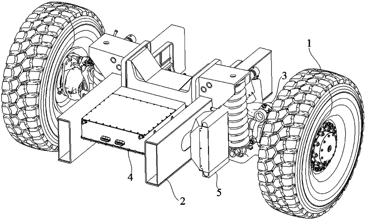
[0033] The embodiments of the present application provide an electric drive traveling unit that meets the universality requirements of a multi-axle high-mobility off-road vehicle for a wheel-side motor drive device.

[0034] In order to better understand the above technical solutions, the above technical solutions will be described in detail below in conjunction with the accompanying drawings and specific implementation methods. It should be understood that the embodiments of the present invention and the specific features in the embodiments are detailed descriptions of the technical solutions of the present application. , rather than limiting the technical solutions of the present application, the embodiments of the present application and the technical features in the embodiments can be combined without conflict.

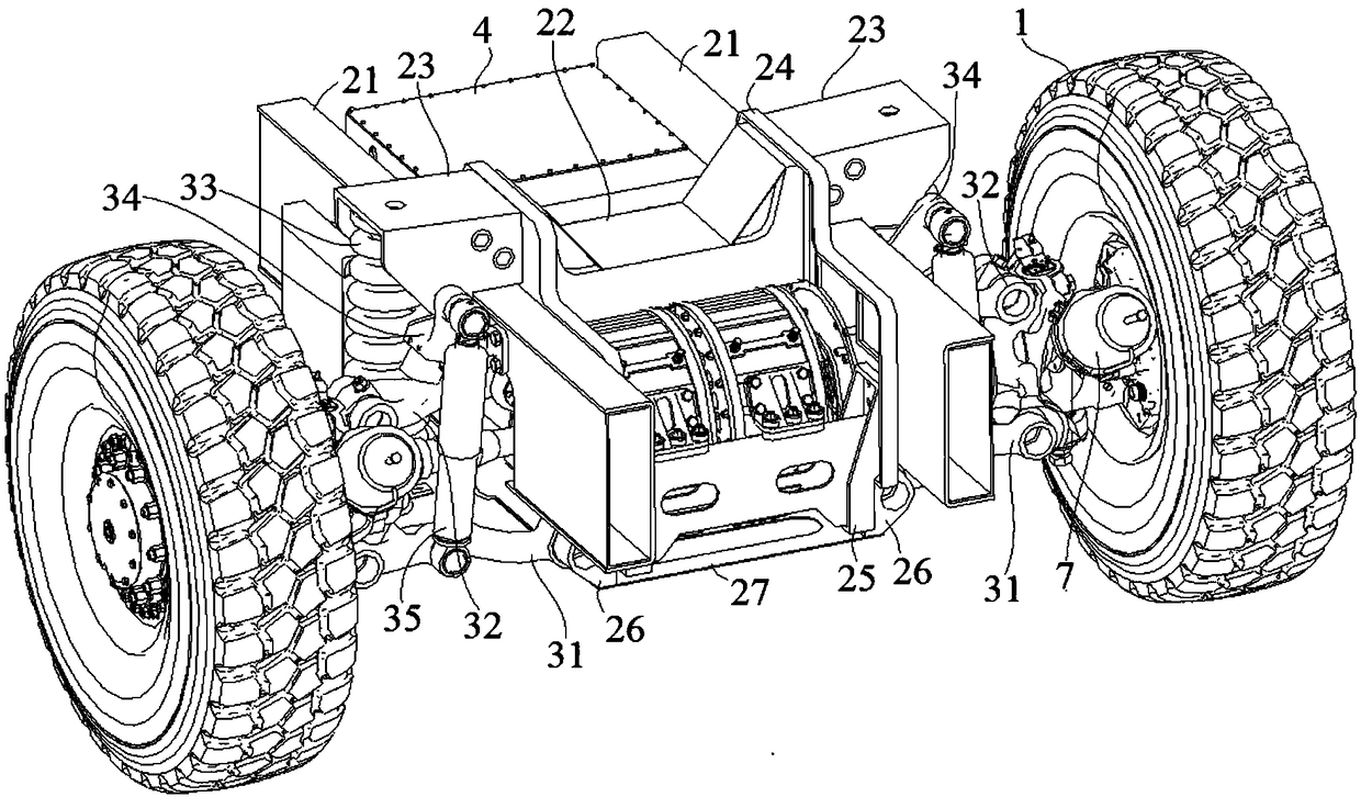
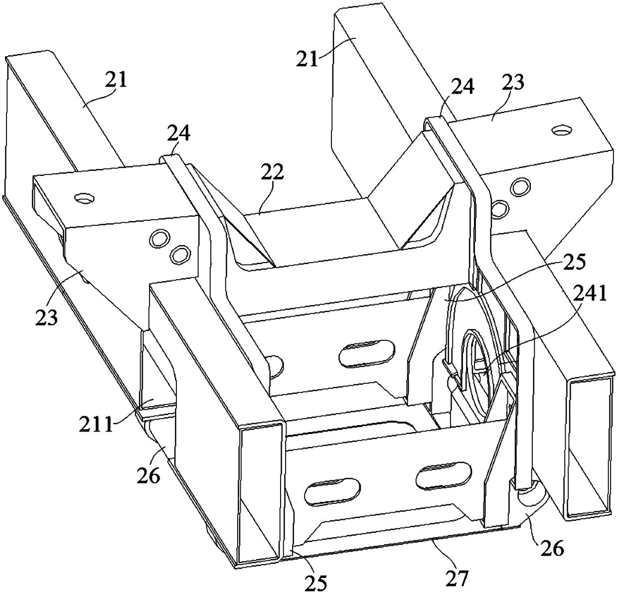
[0035] see figure 1 with figure 2 , a modular electric drive driving unit, including: a modular frame assembly 2, a drive motor, a wheel drive shaft, a wheel hu...


PUM


Abstract

The invention belongs to the technical field of special electric drive vehicles, and discloses a modular electric drive travel unit which comprises a modular vehicle frame assembly, drive motors, wheel-side transmission shafts, wheel hub and brake assemblies, vehicle wheels, a double-wishbone independent suspension, motor coolers and a motor controller. The modular vehicle frame assembly comprisestwo longitudinal beams, two motor mounting side plates, a suspension transverse beam, two motor mounting transverse beams and a bottom protection plate; the two motor mounting side plates are fixed onto the inner side surfaces of the two longitudinal beams, and two ends of the suspension transverse beam are fixed onto the longitudinal beams by the aid of fixing components; two ends of each motormounting transverse beam are fixed to positions between the two motor mounting side plates, the bottom protection plate is fixed to the bottoms of the motor mounting transverse beams, and motor mounting frame structures are formed; the drive motors are fixed into the motor mounting frame structures and are connected with the vehicle wheels sequentially by the wheel-side transmission shafts and thewheel hub and brake assemblies; the double-wishbone independent suspension is arranged between the wheel hub and brake assemblies and the modular vehicle frame assembly in a connected manner.

Description

technical field [0001] The invention relates to the technical field of special electric drive vehicles, in particular to a modular electric drive driving unit and a multi-axle driving unit. Background technique [0002] In the prior art, in the layout setting of the vehicle, the focus is on the structure and layout of the drive motor. The layout of other structures is usually based on the type and use of different vehicles, and is set around the drive structure; resulting in suspension, vehicle frame and electric motors. The coordination of the driving device is not stable, especially for special vehicles such as multi-axle vehicles, it cannot meet the generalization and modularization requirements of multi-axle electric drive vehicles, resulting in complex vehicle layout and assembly operations, and poor coordination. It is often manifested in that it takes up a lot of space, it is difficult to arrange and maintain, and the coordination relationship of the vehicle driving s...

Claims


Application Information

Patent Timeline
IPC IPC(8): B62D21/02B60K7/00B60K1/00B60G3/20B60T1/06
CPCB62D21/02B60G3/20B60K1/00B60K7/0007B60T1/06B60K2001/006
Inventor 刘欢魏珣冯炜王宝金
Owner SPECIAL VEHICLE TECH CENT OF HUBEI AEROSPACE TECH RES INST
Learn More