Non-contact metal liquid surface slag layer electromagnetic automatic treatment device and method

A metal liquid surface, non-contact technology, applied in non-electric variable control, metal material coating process, coating, etc., can solve problems such as rough coating, zinc tumor, and affecting the quality of galvanized layer

Active Publication Date: 2019-03-08
SHANGHAI UNIV +1
View PDF5 Cites 10 Cited by
  • Summary
  • Abstract
  • Description
  • Claims
  • Application Information

AI Technical Summary

Problems solved by technology

When the metal plate enters the zinc liquid, the zinc slag may first adhere to the metal plate, forming defects, or bring the zinc slag into the zinc liquid to contaminate the zinc liquid; when the metal plate is pulled out of the zinc liquid, The slag on the surface of the zinc liquid will adhere to the zinc layer of the metal plate, which will seriously affect the quality of the galvanized layer, cause the coating to be rough, and even produce zinc tumors, which will seriously affect the pass rate of the galvanized metal plate
At present, the production process of hot-dip galvanized sheets mostly uses slag rake tools for manual slag removal or mechanical slag removal to reduce the slag near the metal plate, reduce the adhesion of slag, and improve the quality of galvanized workpieces. However, this method of slag removal The efficiency is low, the effect is poor, and the contact with the molten metal during the slag removal process may also pollute the molten metal
[0004] In recent years, with the development of electromagnetic technology, some researchers have used electromagnetic separation or purification technology to remove impurities in molten metal, but there is still no efficient and effective means for removing slag on the surface of molten metal

Method used


Image

  • Non-contact metal liquid surface slag layer electromagnetic automatic treatment device and method
  • Non-contact metal liquid surface slag layer electromagnetic automatic treatment device and method
  • Non-contact metal liquid surface slag layer electromagnetic automatic treatment device and method

Examples


Embodiment 1

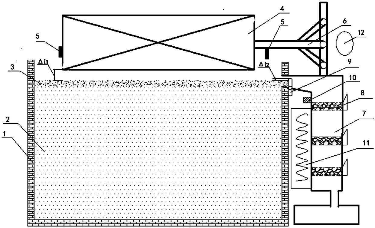
[0047] In this example, see Figure 1 ~ Figure 3 , a non-contact electromagnetic automatic processing device for molten metal level slag layer, comprising a signal processing system 12, an automatic lifting and sliding slag retaining plate 9 and a molten metal container 1 with a slag port, in the molten metal container 1 with a slag port The molten metal 2 is loaded inside, and the slag layer 3 floats on the surface of the molten metal 2. The automatic lifting and sliding slag stopper 9 is set at the position of the slag mouth of the molten metal container 1 with a slag mouth, forming a liftable slag stop device , the signal processing system 12 can control the height of the upper edge of the automatic lifting and sliding slag retaining plate 9, and is provided with a non-contact metal liquid surface slag layer electromagnetic automatic slag removal processing device 20, and a non-contact metal liquid surface slag layer electromagnetic automatic slag removal The slag processin...

Embodiment 2

[0068] This embodiment is basically the same as Embodiment 1, especially in that:

[0069] In this example, see Figure 4 , the non-contact metal liquid surface slag layer electromagnetic automatic treatment device is arranged in the hot dip coating device, and the molten metal container 1 with the slag mouth is used as the container of the hot dip coating device at the same time, and the molten metal container 1 with the slag mouth The molten metal 2 is used as the metal plating solution of the hot-dip plating process, and the metal base strip 17 to be treated in the hot-dip plating process passes through the first conveying roller 19 in the furnace nose 18 of the molten metal container 1 with a slag mouth, so that the metal base strip 17 is immersed in In the molten metal 2 in the molten metal container 1 with the slag mouth, the metal substrate 17 part immersed in the molten metal 2 is subjected to hot-dip plating through the sinking roller 21 arranged in the molten metal 2...

Embodiment 3

[0078] This embodiment is basically the same as the previous embodiment, and the special features are:

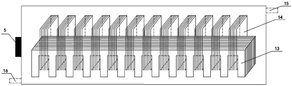
[0079] In this embodiment, the non-contact metal liquid surface slag layer electromagnetic automatic treatment device is arranged in the hot dip coating device, and the metal liquid container 1 with the slag opening is used as the hot dip coating device container at the same time, and the slag opening is used as the container of the hot dip coating device. The molten metal 2 in the molten metal container 1 is used as the metal plating solution of the hot-dip plating process, and the traveling wave magnetic field generator 4 is arranged at a position of 10 mm from the workpiece to be processed in the hot-dip plating process, and is to be processed in the hot-dip plating process At least one side of the workpiece is provided with a traveling wave magnetic field generator 4 . In this embodiment, the non-contact metal liquid level slag layer electromagnetic automatic treatment ...


PUM


Abstract

The invention provides a non-contact metal liquid surface slag layer electromagnetic automatic treatment device and method. A traveling wave magnetic field generator is placed above a metal liquid surface slag layer, does not make contact with the metal liquid surface slag layer, and generates a traveling wave magnetic field by introducing an alternating current to interact with metal liquid to generate electromagnetic force, the electromagnetic force pushes the metal liquid to move towards a slag opening, the flowing metal liquid drives the slag layer through the effect of shearing force to enter a slag filter through an automatic lifting sliding baffle at the slag opening, floating slag with the small amount of metal liquid flows through a slag filtering layer to be filtered out, the metal liquid flows to the lower part of the slag filter for recycle. According to the non-contact metal liquid surface slag layer electromagnetic automatic treatment method, the positions of the traveling wave magnetic field generator and an automatic lifting slag baffle are adjusted in real time so as to achieve the optimal slagging-off effect, the power of a heating device is adjusted in real timeto heat the slag filter, thus the metal liquid or the slag are prevented from being solidified to plug the slag filter, and liquid metal in a container is subjected to heat compensation. The non-contact metal liquid surface slag layer electromagnetic automatic treatment device is high in slagging-off efficiency, can treat the slag in real time and recycle the metal liquid in time, and a process iseasy to operate and easy to popularize.

Description

technical field [0001] The invention relates to a metal liquid production and treatment process and device, in particular to a metal liquid surface slag layer treatment device and method, which are applied in the technical field of metal smelting process or hot-dip plating chemical process. Background technique [0002] In the field of metal technology, slag will inevitably be produced, and these slags will often affect product quality, product qualification rate and production efficiency. During the process of process treatment or production and use, for the molten liquid metal held in the container, there are generally three types of slag in the container: the bottom slag deposited in the lower part of the molten metal, which can be manually disposed of when production is stopped; the slag suspended in the The slag inside the molten metal can be treated by physical and chemical reaction methods; the slag floating on the surface of the metal liquid is composed of the oxidat...

Claims


Application Information

Patent Timeline
Patent Type & Authority Applications(China)
IPC IPC(8): C23C2/00C21C7/00G05D27/02
CPCG05D27/02C21C7/0087C23C2/003Y02P10/20
Inventor 雷作胜张晓良孙晓辉李彬卢海彪
Owner SHANGHAI UNIV
Why Eureka
Try Eureka