
Bin electronic lock

A technology for electronic locks and cabinets, applied in the field of electronic locks, can solve the problems of high mechanical failure rate, many parts, complex structure, etc., and achieve the effect of low mechanical failure rate, convenient operation and few parts.

Inactive Publication Date: 2019-03-08
XIAMEN HEADLEADER TECH CO LTD
View PDF6 Cites 4 Cited by
  • Summary
  • Abstract
  • Description
  • Claims
  • Application Information

AI Technical Summary

Problems solved by technology

However, this new type of electronic lock also has the following disadvantages: the motor controls the swing of the limiter through a mechanical transmission mechanism composed of a gear reduction group, a push rod, etc. assembly, high mechanical failure rate

Method used


Image

  • Bin electronic lock
  • Bin electronic lock
  • Bin electronic lock

Examples


Embodiment Construction

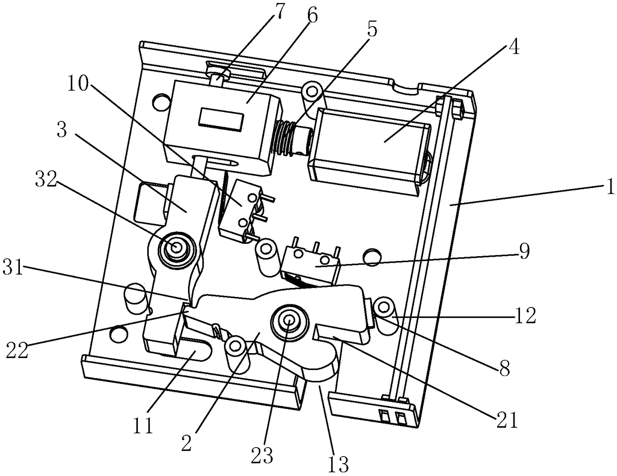
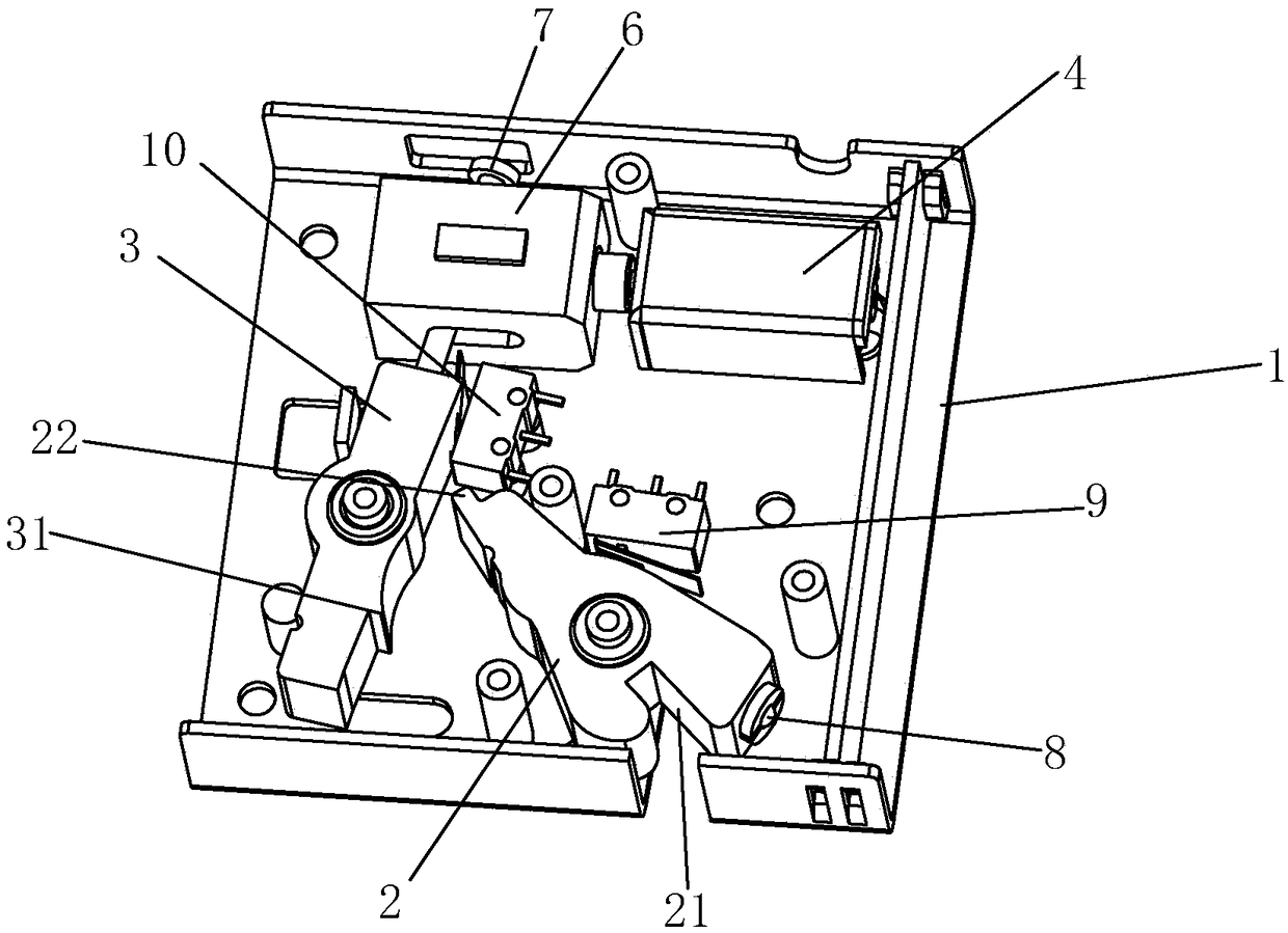
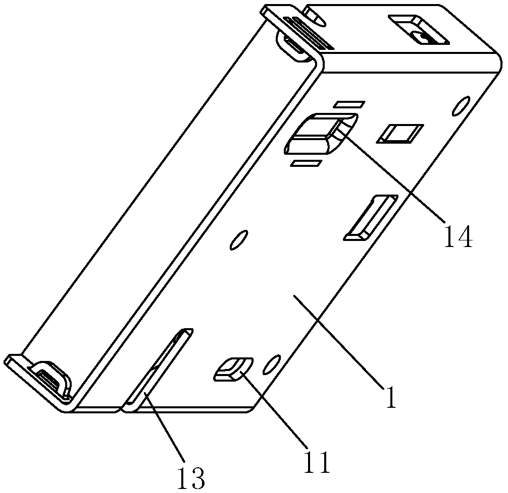
[0023] Examples, see Figure 1-Figure 4 As shown, a cabinet electronic lock of the present invention includes a lock case 1, a lock body 2, a limiter 3, a motor 4, and a main control board (not shown in the figure), and the lock body 2 and the limiter 3 rotate respectively Connected to the lock case 1, and between the lock body 2 and the lock case 1, there is a first elastic member for providing the reset of the lock body 2. The lock body 2 is provided with a card slot 21 that cooperates with the lock hook on the door. The lock body 2 and the limiting member 3 are matched with a stop structure. The core structure of the main control board adopts the SONIX2501B single-chip microcomputer chip to cooperate with the L9170 (or RZ7899) motor driver chip to realize, the motor 4 is electrically connected with the main control board, and the motor 4 is connected with the limiter 3 through the transmission mechanism. The transmission mechanism includes a slider 6 and a screw 5, the sli...


PUM


Abstract

The invention discloses a bin electronic lock. The bin electronic lock comprises a lock shell, a lock body, a limiting part, a motor and a main control panel. The lock body and the limiting part are rotationally connected to the lock shell, and a first elastic part allowing the lock body to reset is arranged between the lock body and the lock shell in an abutting manner. The lock body is providedwith a clamp groove matched with a lock hook on a door. The lock body and the limiting part are provided with a locking structure in a cooperation manner. The motor is electrically connected with themain control panel and is in transmission connection with the limiting part through a transmission mechanism. The transmission mechanism comprises a sliding block and a screw, and the sliding block isarranged on the lock shell in a sliding manner through a sliding guide structure and is movably connected with the limiting part. The screw is driven by the motor to rotate and is in threaded connection with the sliding block so as to drive the sliding block to slide. The transmission mechanism of the bin electronic lock is provided with few components, the structure is quite simple, assembling is convenient, and the mechanical failure rate is low.

Description

technical field [0001] The invention relates to an electronic lock, in particular to an electronic lock for a cabinet. Background technique [0002] Electronic locks for cabinets generally include a lock case, a lock body, a limiter and other components. The parts are matched with a stop structure. The traditional cabinet electronic lock uses an electromagnetic mechanism to control the swing of the limiter, so that it cancels the limit on the lock body and achieves the purpose of opening the door. However, the electromagnetic mechanism needs to be driven by a large current and consumes a lot of power. For this reason, in the prior art, a new type of cabinet electronic lock that uses a motor in conjunction with a mechanical transmission mechanism to control the swing of the limiter has appeared. This electronic lock is driven by a motor and has the characteristics of low current, low cost, and not easily damaged. However, this new type of electronic lock also has the follow...

Claims


Application Information

Patent Timeline
Patent Type & Authority Applications(China)
IPC IPC(8): E05B65/52E05B47/00E05B17/20
CPCE05B17/2019E05B47/0012E05B47/0607E05B65/0042E05B2047/0069E05B2047/0018E05B2015/041E05C3/24E05B2047/0065E05B2047/0016E05B9/02E05B15/04E05B17/22E05B2015/0448E05B2047/0017E05Y2900/20E05B17/0029
Inventor 刘颋鹏林君敏张佳生陈炳煌
Owner XIAMEN HEADLEADER TECH CO LTD
Learn More