Test method of double shield TBM tunneling tunnel surrounding rock rebound value

A test method and technology of rebound value, which are applied in tunnels, tunnel linings, earthwork drilling, etc., can solve the problems of limited observation range, error in observation results, interference of tunnel driving operations, etc., to achieve convenient measurement, intuitive measurement results, and accurate measurement. Equipment simple effect

Active Publication Date: 2019-03-08
CHINA HYDROELECTRIC ENGINEERING CONSULTING GROUP CHENGDU RESEARCH HYDROELECTRIC INVESTIGATION DESIGN AND INSTITUTE
View PDF7 Cites 2 Cited by
  • Summary
  • Abstract
  • Description
  • Claims
  • Application Information

AI Technical Summary

Problems solved by technology

Due to the large number of interference sound sources at the construction site, the reliability of the test and analysis conclusions is not high, and it can only detect the hard surrounding rock sections where rockbursts may occur. This method will also cause serious interference to the tunnel excavation operation
[0005] (3) About 0.1m from the side of the TBM backing 2 observation window to observe the characteristics of surrounding rock and its development trend, but it will also cause serious interference to the tunnel excavation operation, and there will be safety hazards for the observers. Secondly, the observation range is very limited, and there are large errors in the observation results.
[0006] (4) Geological engineers enter the tunnel face in front of the cutter head for direct observation and mapping. This method has a large observation range and strong intuition, and the observation analysis and judgment conclusions are relatively reliable, but it is only suitable for tunnel faces with better and stable surrounding rocks. Otherwise, there will be a high safety risk for the observers, and they will need to stop for observation, which will seriously affect the efficiency of tunneling operations

Method used


Image

  • Test method of double shield TBM tunneling tunnel surrounding rock rebound value
  • Test method of double shield TBM tunneling tunnel surrounding rock rebound value

Examples


Embodiment Construction

[0029] The present invention will be further described below in conjunction with the accompanying drawings and specific embodiments.

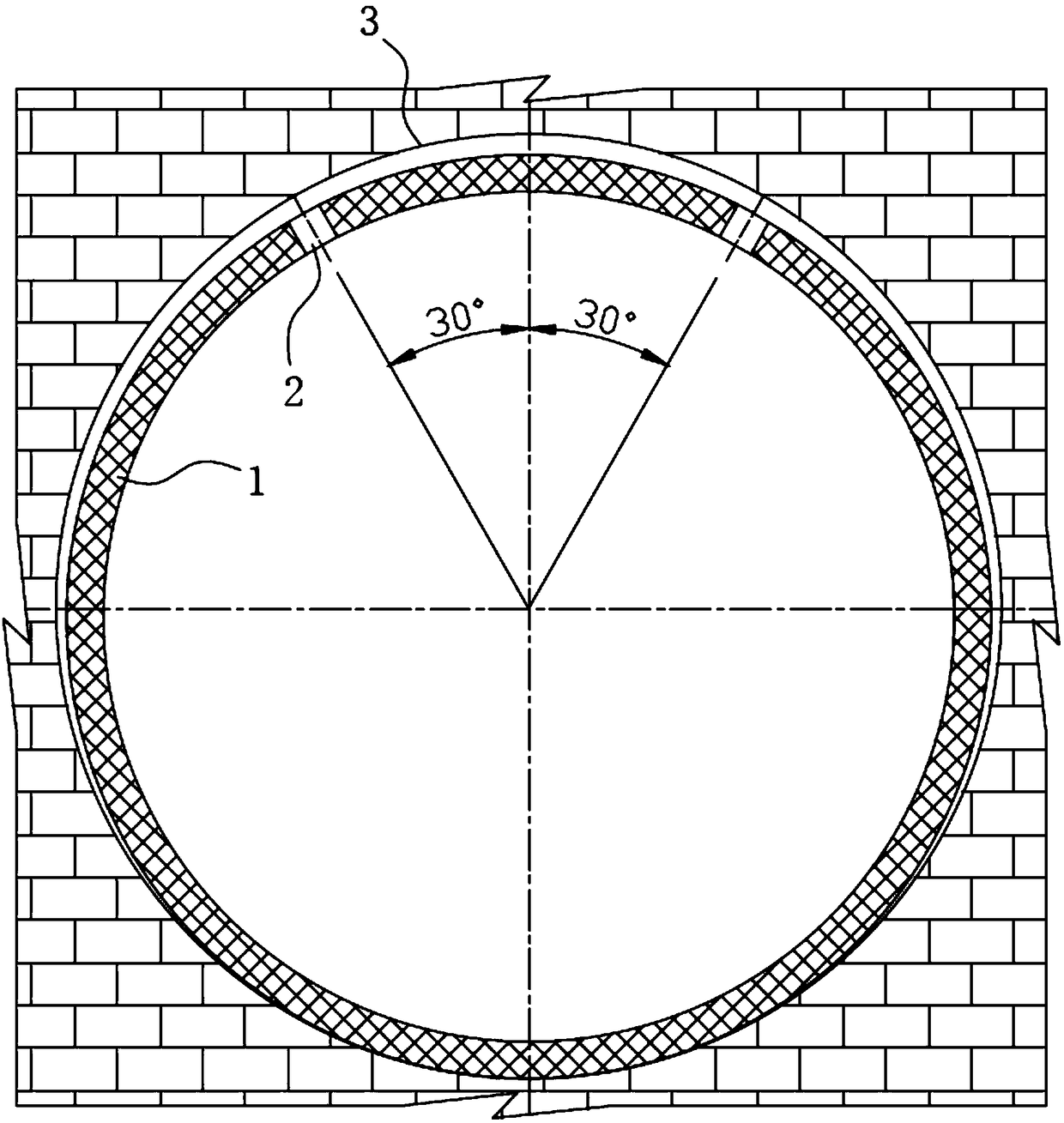
[0030] Such as figure 1 and figure 2 Shown in, the double-shield TBM excavation tunnel surrounding rock rebound value test method of the present invention, in the double-shield TBM excavation process, described surrounding rock rebound value test method comprises the following steps:

[0031] Step A, remove the tail shield after the corresponding segment 1 is installed;

[0032] Step B, filling the gap between the segment 1 and the rock wall 3 through the backfill hole 2 reserved on the segment 1;

[0033] Between the above steps A and B, the following steps C and D are also included:

[0034] Step C, opening the corresponding backfill hole 2 on the segment 1, and cleaning the loose rock mass in the backfill hole 2;

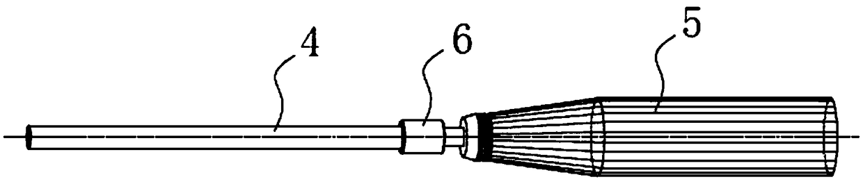
[0035] Step D, insert a rigid extension rod 4 into the backfill hole 2, and make one end of the extension rod 4 contact wit...


PUM


Abstract

The invention discloses a test method of double shield TBM tunneling tunnel surrounding rock rebound value, and belongs to the technical field of TBM tunnel construction. The invention provides a novel test method aiming at double shield TBM tunnel surrounding rock rebound value. The test method utilizes reserved backfill holes of duct pieces in the process of double shield TBM tunneling. After the corresponding duct pieces are installed and a tail shield is removed, and within the time slot before hydraulic fill and grouting, rebound values K of rock mass on the bottoms of the backfill holesare measured through a rebound apparatus and corresponding extension rods, and whether the surrounding rocks near the corresponding backfill holes are stable determined by the measured rebound valuesK. The test method of double shield TBM tunneling tunnel surrounding rock rebound value has the advantages of convenient measurement, simple measuring equipments, visualized and precise measuring results, and the machine does not need to be stopped in the measurement process and tunnel tunneling construction cannot be subjected to a large effect, and thus the test method can be widely popularizedand used.

Description

technical field [0001] The invention relates to the technical field of TBM tunnel construction, in particular to a method for testing the rebound value of the surrounding rock of a double-shield TBM excavation tunnel. Background technique [0002] In tunnel excavation construction methods, the use of tunnel boring machine (TBM) has become the most common construction method at present. TBMs are usually divided into open type, single shield type and double shield type. Among them, the double-shield TBM has the best adaptability to geological conditions, and the excavation and segment installation are carried out at the same time, which can absolutely guarantee the safety of construction personnel, so it is the most commonly used TBM equipment for tunnel excavation. However, during the excavation process of double-shield TBM, it is often difficult to directly observe and detect the characteristics of the surrounding rock and its changes, which makes it difficult to effectively...

Claims


Application Information

Patent Timeline
Patent Type & Authority Applications(China)
IPC IPC(8): E21D9/087E21D11/08E21F17/18
CPCE21D9/0607E21D9/087E21D11/08E21F17/18
Inventor 陈炜韬傅支黔曾建军张子晗唐辉
Owner CHINA HYDROELECTRIC ENGINEERING CONSULTING GROUP CHENGDU RESEARCH HYDROELECTRIC INVESTIGATION DESIGN AND INSTITUTE
Why Eureka
Try Eureka