Sound pressure sensitivity calibration cavity and testing method thereof

A technology of sensitivity and standard cavity, which is applied in the field of sound pressure sensitivity calibration cavity and its testing, can solve the problems that the coupled cavity reciprocity method cannot realize the phase sensitivity calibration, the limitation of the test object, the uncertainty of the sound pressure sensitivity measurement, etc., and achieve the acoustic emission Good performance and reciprocity, realize phase sensitivity calibration, and reduce measurement error

Active Publication Date: 2019-03-08
THE 715TH RES INST OF CHINA SHIPBUILDING IND CORP
View PDF9 Cites 6 Cited by
  • Summary
  • Abstract
  • Description
  • Claims
  • Application Information

AI Technical Summary

Problems solved by technology

The three-transducer coupling cavity reciprocity method has the following aspects to be improved. First, the measurement of sound pressure sensitivity is uncertain, such as the sound pressure sensitivity of the high static pressure coupling cavity standard device of the national defense technology industry underwater acoustic first-level metering station. = 0.5dB, k = 2, which needs to be further reduced; 2. In order to meet the uniform condition of the sound field inside the coupling cavity, the internal size of the coupling cavity is small, so it can only be calibrated to a specific hydrophone with a small size, and the test object is greatly limited; 3. The conventional coupling cavity reciprocity method cannot achieve phase sensitivity calibration. When hydrophones are used in an array, phase sensitivity is a very important performance index

Method used


Image

  • Sound pressure sensitivity calibration cavity and testing method thereof
  • Sound pressure sensitivity calibration cavity and testing method thereof
  • Sound pressure sensitivity calibration cavity and testing method thereof

Examples


Embodiment Construction

[0021] The present invention will be described in detail below in conjunction with accompanying drawing:

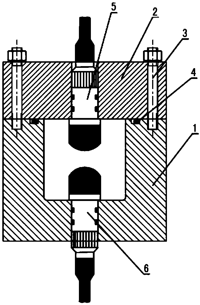
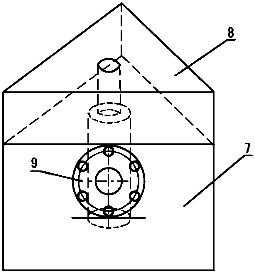
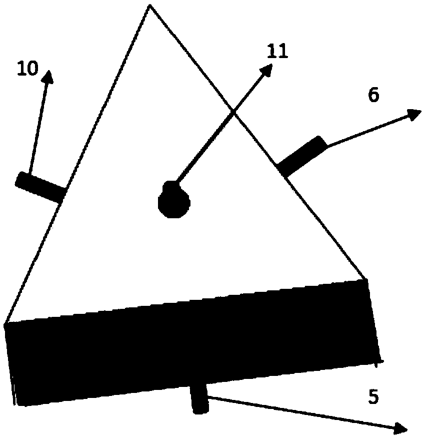
[0022] The technical scheme adopted in the present invention: a sound pressure sensitivity calibration cavity and its testing method, the cavity body is composed of a standard cavity and a measuring cavity, and the testing method is the four-transducer reciprocal method, that is, firstly, the standard cavity is used to transmit The transducer and the reciprocal transducer are used to measure the transfer impedance and the reciprocal constant J of the coupling cavity, and then the transmitting transducer, the reciprocal transducer, and the hydrophone under test are installed in the measurement cavity, and another auxiliary transmitting The transducer transmits signals, and the first three are used as receivers, so as to realize the calibration of sound pressure sensitivity and phase sensitivity.

[0023] The standard cavity must be small enough for the lumped parameter mod...


PUM


Abstract

The invention discloses a sound pressure sensitivity calibration cavity and a testing method thereof. The calibration cavity consists of two rigid cavities which are a standard cavity and a measuringcavity; the standard cavity is a small volume cavity whose internal and external are in cylindrical shapes, and a transmitting transducer and a reciprocal transducer are installed in the standard cavity during measuring, so that the accurate measuring on standard cavity reciprocal constants and the transfer impedance of the transmitting transducer and the reciprocal transducer can be accomplished;and the internal of the measuring cavity is in a cylindrical shape, and the external of the measuring cavity is a triangular rigid cavity, and during measuring, the transmitting transducer, the reciprocal transducer and a measured hydrophone are respectively fixed on three faces of the triangular cavity, located on the central face of the cylindrical inner cavity and in symmetric distribution. The testing method is a four-transducer reciprocity method. The beneficial effects of the calibration cavity and testing method are that through the calibration by using the double coupled cavity and the four-transducer reciprocity method, the measuring precision of low frequency sound pressure sensitivity can be enhanced, and the measuring on the phase of the hydrophone in the coupled cavity can berealized.

Description

technical field [0001] The invention relates to the field of underwater acoustic measurement, and mainly relates to a sound pressure sensitivity calibration cavity and a testing method thereof. Background technique [0002] Hydrophones are widely used in underwater acoustic signal reception, underwater noise monitoring, underwater acoustic measurement and other fields. Sound pressure sensitivity is the most important technical index of hydrophones. Low-frequency sound pressure sensitivity is usually measured under free-field conditions in open water, and is limited by the space and frequency of the sound field. If no special signal processing is performed, the lower limit frequency is usually above 1kHz. In order to solve the low-frequency measurement problem, many other measurement methods have been developed successively, such as the vibrating liquid column method, piezoelectric compensation method, coupled cavity reciprocity method, etc. The vibration liquid column metho...

Claims


Application Information

Patent Timeline
Patent Type & Authority Applications(China)
IPC IPC(8): G01H3/00
CPCG01H3/005
Inventor 何涛王少博王世全
Owner THE 715TH RES INST OF CHINA SHIPBUILDING IND CORP
Why Eureka
Try Eureka