
Cold zone tunnel longitudinal temperature experimental device involving train piston wind factor

A technology for tunnels and experimental devices in cold regions, applied to measuring devices, railway vehicle testing, instruments, etc., can solve problems such as many assumptions, difficulty in meeting engineering needs, icing, etc., to ensure driving safety, reduce construction costs, and improve The effect of economic efficiency

Pending Publication Date: 2019-03-08
中铁西南科学研究院有限公司
View PDF0 Cites 2 Cited by
  • Summary
  • Abstract
  • Description
  • Claims
  • Application Information

AI Technical Summary

Problems solved by technology

[0003] At present, for tunnels in medium and short cold regions, the same anti-freezing and thawing measures are usually adopted in the whole tunnel, and the thickness of the insulation layer is the same. Although as the number of long tunnels continues to increase, the way of laying insulation layers at both ends of long tunnels is also considered. However, the laying length is basically based on foreign experience formulas or engineering analogy methods, which do not conform to the actual situation in my country. There are no technical specifications and data for reference in the design parameters of freeze-thaw protection for tunnels in cold regions.
[0004] In addition, with the opening and operation of high-speed railways in cold regions, some new problems related to the temperature distribution in the tunnel have emerged. For example, the Harbin-Dalian high-speed railway that has been in operation has brought cold energy into the tunnel in winter, causing temperature redistribution. The problem caused the original positive temperature section in the long tunnel to be responsible, resulting in icing, which brought hidden dangers to the safety of high-speed trains
[0005] Using the method of field testing of the on-site tunnel, the results obtained are the most realistic and can best meet the actual situation, and can provide accurate parameters for the laying length of the insulation layer, but there are two problems. One is that the test results can only represent a specific tunnel. Longitudinal temperature distribution of the tunnel, there are many factors affecting the longitudinal temperature distribution of the tunnel, such as: the average temperature of the coldest month at the entrance of the tunnel, natural wind speed, wind direction, tunnel length, etc. There are certain limitations in popularization and application. A large amount of manpower, material and financial resources, large amount of engineering, general economical practicability, and the method of on-site testing can also be used for long highway tunnels, but it is almost impossible to conduct temperature testing in the operation line for high-speed railways; second, only when the tunnel is completed Only the data test results after opening to traffic can represent the actual longitudinal temperature distribution of the tunnel. The field test has serious lateness, and it is difficult to meet the actual needs of the design.
Theoretical analysis is too idealistic, with too many assumptions, and it is difficult to meet engineering needs. Even if it can meet the needs, it needs to be verified
Therefore, generally speaking, there is a lack of an effective method for studying the longitudinal temperature distribution of tunnels in cold regions for long tunnels in cold regions, especially for the temperature distribution of high-speed railway tunnels under piston wind conditions.

Method used


Image

  • Cold zone tunnel longitudinal temperature experimental device involving train piston wind factor
  • Cold zone tunnel longitudinal temperature experimental device involving train piston wind factor
  • Cold zone tunnel longitudinal temperature experimental device involving train piston wind factor

Examples


Embodiment 2

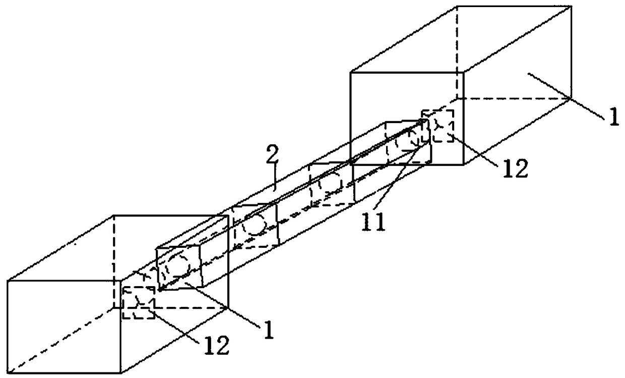
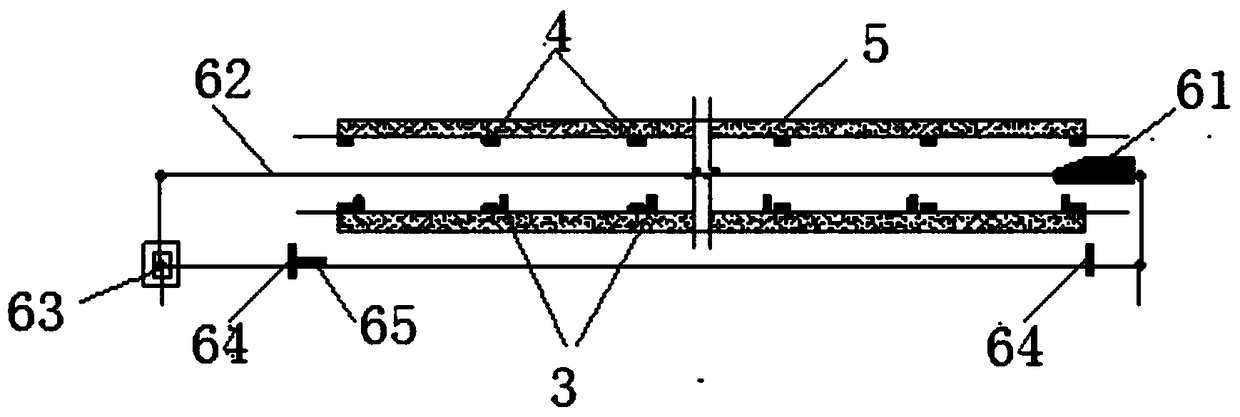
[0027] like Figure 1-6 As shown, the tunnel longitudinal temperature experiment device in the cold area involving the train piston wind factor includes a constant temperature warehouse 1, which is composed of a refrigeration system and a warehouse. There are 2 rooms in total, one main and one auxiliary. Warehouse 1 is mobile and can move freely. The temperature in the warehouse can be precisely controlled through the refrigeration system. There is a circular hole on one side of the warehouse (it can also be a tunnel-shaped hole for the experiment to be more realistic). The size of the circular hole 11 is consistent with the inner diameter of the tunnel model. The four corners of the lower part of the auxiliary constant temperature warehouse 1 are equipped with pulleys, which can move freely, thereby providing a more convenient cold source for experiments.

[0028] The wind speed control device is installed in the warehouse with an axial flow fan 12 at a distance of 1110-20cm...


PUM


Abstract

The invention discloses a cold zone tunnel longitudinal temperature experimental device involving a train piston wind factor. The device comprises a constant temperature warehouse, a wind speed control device, a tunnel model, a train model device, a thermostatic bath, wind speed sensors, temperature sensors, and a data acquisition system; the constant temperature warehouse is used for providing acold source; the wind speed control device is used for providing wind energy; tunnel model units are spliced to form the tunnel model; the thermostatic bath is composed of thermostatic bath units which are independently arranged; the thermostatic bath unit wraps the outer surface of the corresponding tunnel model unit; and the wind speed sensors and the temperature sensors are disposed in the tunnel model and are electrically connected with the data acquisition system. With the experimental device for testing the longitudinal temperature distribution law of tunnels in a cold zone under a one-way or two-way ventilation condition provided by the invention adopted, the distribution law of the longitudinal temperature of long tunnels under the conditions of different tunnel lengths, differenttunnel portal temperatures, different tunnel portal wind speeds, different surrounding rock initial temperatures and the like can be simulated; and accurate parameters can be provided for the laying length of the insulation layers of the long tunnels in the cold zone.

Description

technical field [0001] The invention relates to a tunnel experiment device in a cold region, in particular to a tunnel longitudinal temperature experiment device in a cold region related to the wind factor of a train piston. Background technique [0002] In high-latitude areas such as Northwest and Northeast my country, as well as high-altitude areas in western my country, more and more tunnels are being built, and the length of the tunnels is also getting longer and longer. In the Ya'an-Nyingchi section of the Sichuan-Tibet Railway, the proportion of tunnels exceeds 90%. It is estimated that there are more than 7 tunnels with a length of more than 30km, and some tunnels are above 4200m above sea level. [0003] At present, for tunnels in medium and short cold regions, the same anti-freezing and thawing measures are usually adopted in the whole tunnel, and the thickness of the insulation layer is the same. Although as the number of long tunnels continues to increase, the way...

Claims


Application Information

Patent Timeline
Patent Type & Authority Applications(China)
IPC IPC(8): G01M17/08G01N25/00
CPCG01M17/08G01N25/00
Inventor 郑波吴剑刘志强王刚郭瑞史宪明刘玉勇杜俊师亚龙
Owner 中铁西南科学研究院有限公司
Learn More