IGBT multi-parallel module driving circuit

A drive circuit, parallel technology, applied in the direction of electrical components, output power conversion devices, etc., can solve problems such as common emitter circulation, circuit balance, etc., achieve the effect of reducing fault points, simple circuit design, and satisfying the synchronous operation of the test

Pending Publication Date: 2019-03-08
HANGZHOU COMMNET
View PDF0 Cites 2 Cited by
  • Summary
  • Abstract
  • Description
  • Claims
  • Application Information

AI Technical Summary

Problems solved by technology

Therefore, it is particularly important to study the driving method of the IGBT tube. In the prior art, a single-drive IGBT parallel circuit is used in high-power places, and there are problems such as common emitter circulation and circuit balance.

Method used


Image

  • IGBT multi-parallel module driving circuit

Examples


Embodiment 1

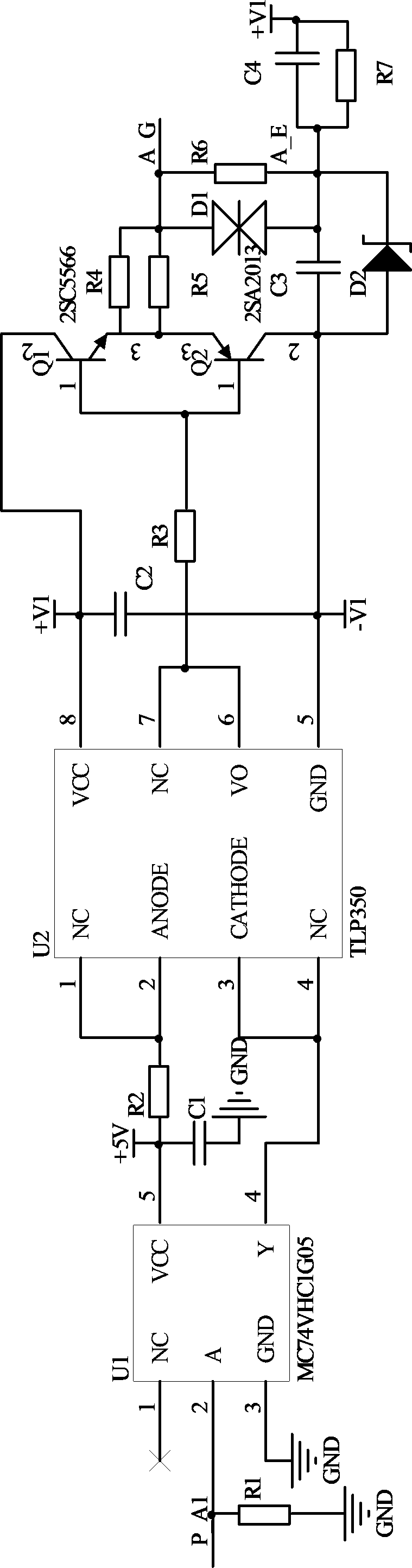
[0018] Such as figure 1 As shown, the IGBT multi-parallel module drive circuit described in this embodiment is composed of multiple IGBT single-module drive circuits connected in parallel. The IGBT single-module drive circuit includes:

[0019] Inverter open-drain output module U1; optocoupler U2; resistor R1, resistor R2, resistor R3, resistor R4, resistor R5, resistor R6, resistor R7; non-polar capacitor C1, non-polar capacitor C2, non-polar capacitor C3, Non-polar capacitor C4; NPN transistor silicon transistor Q1, PNP transistor silicon transistor Q2; bidirectional regulator D1; voltage regulator diode D2;

[0020] One end of the resistor R1 is connected to pin 2 of the open-drain output module U1 of the inverter; pin 5 of the open-drain output module U1 of the inverter is connected to one end of the resistor R2 and one end of the non-polar capacitor C1, and the other end of the resistor R2 , Pin 1 of optocoupler U2 and pin 2 of optocoupler U2 are connected together; pin ...


PUM


Abstract

The invention designs an IGBT multi-parallel module driving circuit, which is composed of a plurality of IGBT single-module driving circuits. The IGBT single-module driving circuit comprises an inverter open-drain output module U1, an optical coupler U2, a resistor R1, a resistor R2, a resistor R3, a resistor R4, a resistor R5, a resistor R6, and a resistor R7, a non-polar capacitor C1, a non-polar capacitor C2, a non-polar capacitor C3, and a non-polar capacitor C4, an NPN tube silicon triode Q1 and a PNP tube silicon triode Q2, a bidirectional voltage-regulator tube D1, and a voltage-regulator diode D2. The driving circuit has the advantages of avoiding a circulation problem, meeting synchronous operation of the test, and being good in the current sharing effect.

Description

technical field [0001] The invention is applied in the field of power electronic product manufacturing, especially an IGBT multi-parallel drive circuit. Background technique [0002] Insulated gate bipolar transistor IGBT, compared with traditional thyristors, IGBT tubes are more suitable for high-power equipment. As the market's demand for megawatt-class high-power equipment is increasing, high-voltage equipment needs to become larger and larger. Generally, it is difficult for a single IGBT tube to reach tens of kilovolts or hundreds of kilovolts, so the IGBT parallel connection scheme has become a trend. The IGBT parallel connection can improve the system's ability to withstand the load current, and at the same time, it can reduce the heat concentration of the module and achieve uniformity. The temperature gradient distribution is beneficial to improve the cycle times. The IGBTs are connected in multi-parallel, which not only takes into account the economy and device rel...

Claims


Application Information

Patent Timeline
Patent Type & Authority Applications(China)
IPC IPC(8): H02M1/088
CPCH02M1/088
Inventor 王亚晶叶骏黄晓龙肖华
Owner HANGZHOU COMMNET
Why Eureka
Try Eureka