
Light positioning device for ultrasonic biological microscope and ultrasonic biological microscope

A positioning device and microscope technology, applied in ultrasonic/sonic/infrasonic diagnosis, application, sonic diagnosis and other directions, can solve the problem that the specific point of the inspection scan cannot be directly and clearly reflected, the physical pain of the patient increases the workload of the doctor, and cannot be retained. image data and other issues, to reduce medical costs, ensure integrity, and avoid missed diagnosis and misdiagnosis.

Pending Publication Date: 2019-03-12
罗晨峻
View PDF0 Cites 2 Cited by
  • Summary
  • Abstract
  • Description
  • Claims
  • Application Information

AI Technical Summary

Problems solved by technology

However, the existing ultrasonic biomicroscope sends out ultrasonic scanning, and ultrasonic wave is a kind of invisible and intangible high-frequency sound wave. When the UBM scans the eyeball, the section view of the eye can be displayed on the monitor, but it cannot be detected in the eyeball. Accurately mark the location of the lesion on the screen, and cannot intuitively and clearly reflect the specific point of the inspection scan. The operator only makes judgments based on his own senses or experience, which is prone to errors and is not conducive to diagnosis and treatment.
[0004] For example, the lesion is located at the 6 o'clock position of the affected eye. When the operator uses UBM to scan, the UBM has no positioning marks on the surface of the eyeball. The operator does not know what area of ​​the affected eye he has scanned. It is better to scan from one end of the affected eye to the other end. This kind of carpet scanning method is extremely inefficient; and even if the scan is correct, the UBM monitor shows the location of the lesion, but it cannot make positioning marks on the surface of the eyeball. Imaging data cannot be retained. After the inspection, it is difficult to directly judge the specific location of the eye lesion and its range in the eyeball. It is necessary to re-examine the affected eye with an ultrasonic biomicroscope, which not only causes the patient's physical pain Increased the workload of doctors, increased medical costs, and caused a waste of medical resources

Method used


Image

  • Light positioning device for ultrasonic biological microscope and ultrasonic biological microscope
  • Light positioning device for ultrasonic biological microscope and ultrasonic biological microscope
  • Light positioning device for ultrasonic biological microscope and ultrasonic biological microscope

Examples


Embodiment 1

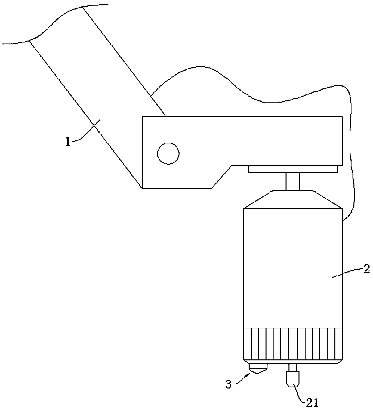
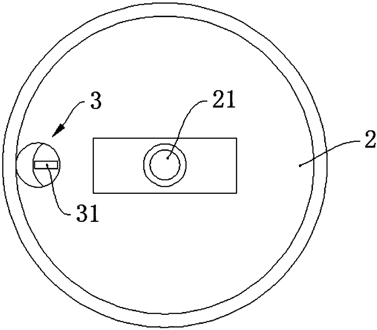
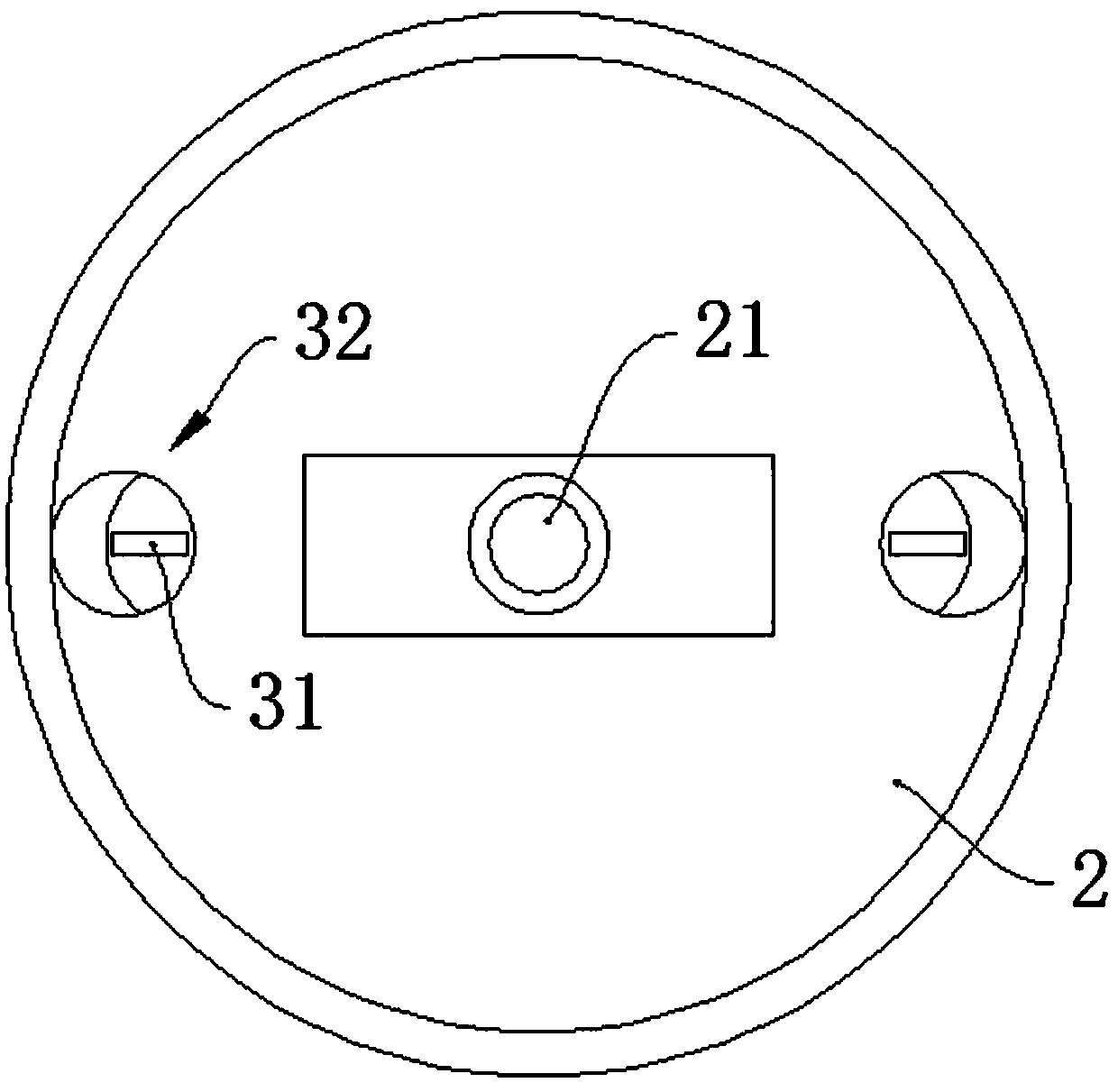
[0050] refer to Figure 1 ~ Figure 4 , a light positioning device for an ultrasonic biological microscope, which includes at least one light source 3, which faces the direction of the transducer 21, and is used to locate the scanning area of ​​the mark transducer 21; for controlling the switch of the light source 3 ;

[0051] Preferably, in this embodiment, the projection of the light emitted by the light source 3 on the eyeball is a strip of light; the light source 3 includes a housing for forming the projection, and the housing is provided with a slit 31 for letting out the light. The slit 31 is strip-shaped. Of course, the dot-shaped projection is also within the protection scope of the present invention, that is, the slit 31 is designed as a small circular hole; as long as the scattered light that can realize light positioning also falls within the protection scope of the present invention.

[0052] The strip projection formed by the light emitted by the light source 3 c...

Embodiment 2

[0064] This embodiment only describes the content that is different from the foregoing embodiments, and the same content will not be described again.

[0065] refer to Figure 5 ~ Figure 7 , a light positioning device for ultrasonic biological microscope, the light emitting source 3 is embedded in the bottom of the probe 2. refer to Figure 7 , In this embodiment, as a further improvement, the bottom of the probe 2 is provided with a transparent cover 35 , and the transparent cover 35 is located on the lower side of the light source 3 .

[0066] Because the eye cup needs to be used during the inspection, the transducer 21 at the lower end of the probe 2 needs to reciprocate in the eye cup, and at this time the distance between the edge of the eye cup and the bottom of the probe 2 is very small. At the bottom of the probe 2, it is easy to bump into the eyecup, affecting the hygienic conditions of the eyecup, and the light source 3 is not convenient for disinfection.

[0067]...

Embodiment 3

[0073] This embodiment only describes the content that is different from the foregoing embodiments, and the same content will not be described again.

[0074] refer to Figure 8 ~ Figure 11 , a light positioning device for an ultrasonic biological microscope, the light source 3 is provided with a slider A34, and the slider A34 is slidably connected to the first chute provided on the outer wall of the probe 2; the first chute is a damping chute.

[0075] In this embodiment, the light source 3 can slide on the peripheral outer wall of the probe 2, and since the first chute is a damping chute, the light source 3 can be fixed at any section of the first chute. It should be noted that the light source 3 is fixed on the top of the probe 2 to realize the function of convenient storage; in the actual use of UBM, the probe 2 will be held and moved, and the light source 3 is stored and fixed on the top of the probe 2. Convenient to hold and pinch the probe 2. When the light source 3 n...


PUM


Abstract

The invention discloses a light positioning device for an ultrasonic biological microscope and ultrasonic biological microscope and belongs to the technical field of ophthalmic medical instruments. The existing ultrasonic biological microscope comprises a mechanical arm (1) and a probe (2), wherein the tail end of the mechanical arm (1) is connected with the top of the probe (2), and the bottom end of the probe (2) is provided with a transducer (21). The light positioning device comprises at least one light-emitting source (3) which faces the pointing direction of the transducer (21) and is used for positioning the scanning area of the marker transducer (21); a switch for controlling the light-emitting source (3); the projection of the light emitted by the light-emitting source (3) on theeyeball coincides with the scanning area of the transducer (21). The light positioning device for ultrasonic biological microscope and ultrasonic biological microscope have the beneficial effects thatthe change process of the scanning position, the scanning range and the scanning path of the transducer can be observed intuitively, the integrity of inspection is ensured, missed diagnosis and misdiagnosis are avoided, and the working efficiency is improved; the light positioning device for an ultrasonic biological microscope and the ultrasonic biological microscope are convenient for rapid positioning during the review, reduces the medical cost and avoids the waste of medical resources.

Description

technical field [0001] The invention belongs to the technical field of ophthalmic medical devices, and in particular relates to a light positioning device for an ultrasonic biological microscope and an ultrasonic biological microscope. Background technique [0002] Ultrasound Biomicroscope (UBM) is a new type of ophthalmic B-ultrasound imaging detection equipment developed in the early 1990s. UBM uses programmable logic devices to control electronic circuits to excite high-frequency ultrasonic sensors to emit high-frequency ultrasonic waves as a signal source, receive ultrasonic echo signals and perform electronic signal processing to obtain digital images related to inspection tissues, combined with computer image processing technology to provide people with Two-dimensional images of the anterior segment similar to low-power optical microscope effects and different cross-sections. UBM has the characteristics of high resolution, real-time, quantitative and not affected by t...

Claims


Application Information

Patent Timeline
Patent Type & Authority Applications(China)
IPC IPC(8): A61B8/10
CPCA61B8/10A61B8/4245
Inventor 罗晨峻张晓帆段文华刘丽娟张晓琼张娟
Owner 罗晨峻
Learn More