Bottle blowing machine installing rack

A technology for installing racks and bottle blowing machines, which is applied in the field of bottle blowing, and can solve problems such as difficulty in guaranteeing processing accuracy, lower matching accuracy of moving parts, inconvenient adjustment of feet, etc., to achieve consistent process and assembly standards, processing and assembly accuracy The effect of high height and consistent installation datum

Pending Publication Date: 2019-03-12
JIANGSU NEWAMSTAR PACKAGING MACHINERY
View PDF6 Cites 1 Cited by
  • Summary
  • Abstract
  • Description
  • Claims
  • Application Information

AI Technical Summary

Problems solved by technology

[0005] The frame is a radial or spoke-shaped frame structure with low overall rigidity, and it is very easy to reduce the matching accuracy of moving parts, deterioration of machine dynamic characteristics or even structural damage due to deformation or other factors during installation and transportation.
[0006] There are too many adjustable feet at the bottom of the frame, and it is inconvenient to adjust the feet in the middle of the frame. It is difficult to adjust all the feet to the same height. The precision of the moving parts such as the cam of the bottom mold causes large vibration and noise, and it is difficult to increase the running speed of the whole machine
[0007] The mounting plate of the manipulator is welded to the frame through a rectangular tube. The mounting surface of the manipulator component is not on the same plane as the mounting surface of other main components. The processing technology of the frame is complex, the processing accuracy is not easy to guarantee, and the maintenance and replacement of the components installed on the frame is inconvenient.

Method used


Image

  • Bottle blowing machine installing rack
  • Bottle blowing machine installing rack
  • Bottle blowing machine installing rack

Examples


Embodiment Construction

[0024] The technical solution of the present invention will be further described below in conjunction with the accompanying drawings.

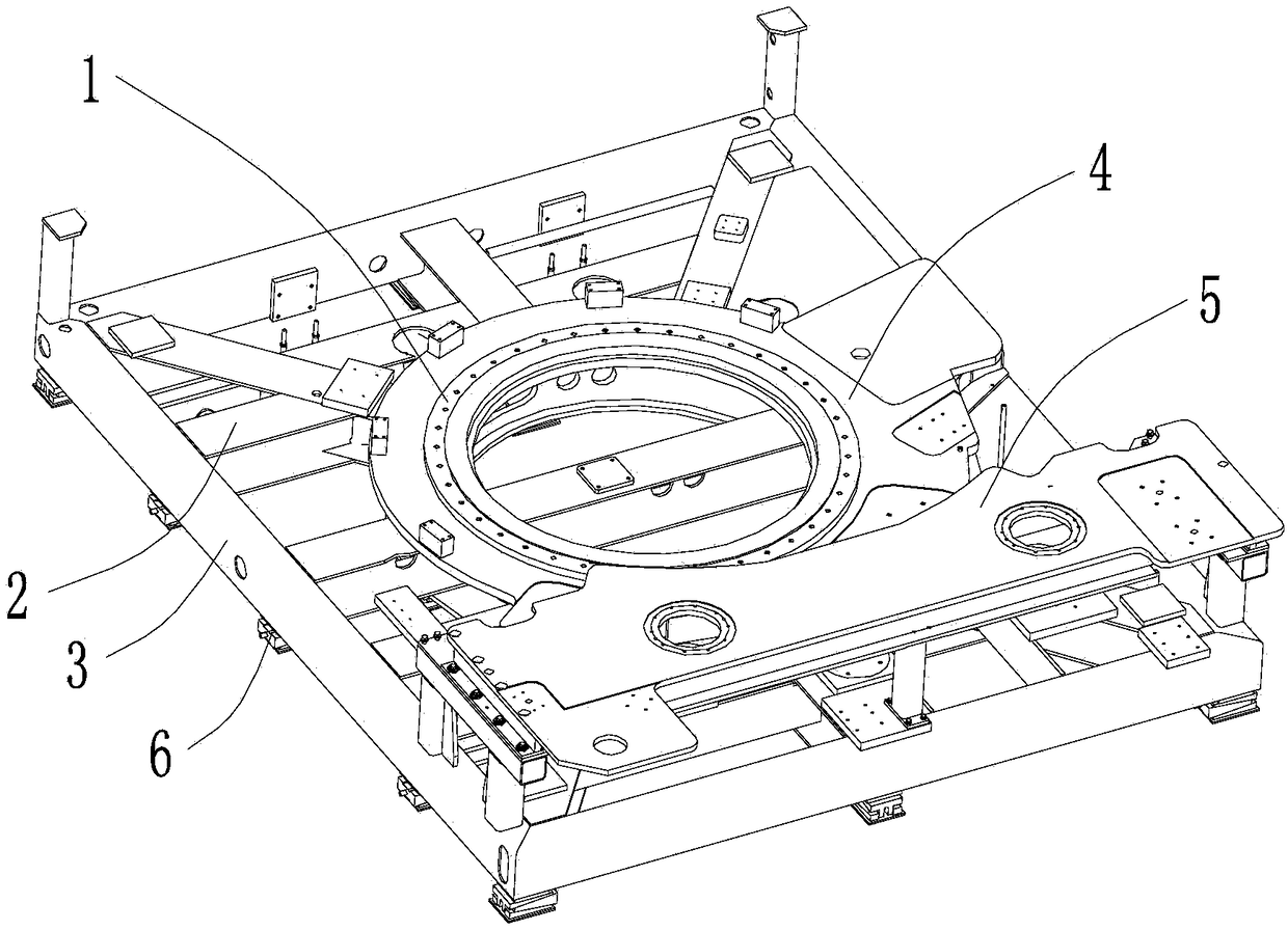
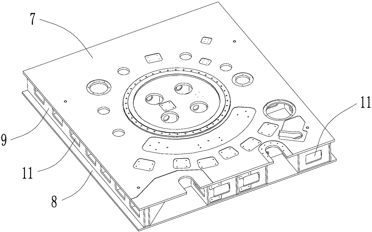
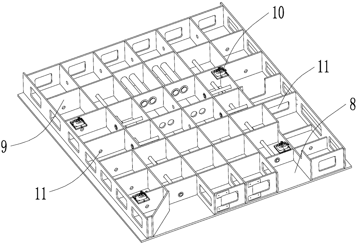
[0025] see Figure 2-4 As shown, the above-mentioned bottle blowing machine installation frame is used for installing the rotary cylinder, transmission assembly, mold frame, stretching assembly, manipulator assembly, cam and support of the blow molding machine and other moving parts. The mounting frame includes an upper panel 7 with a plurality of mounting surfaces processed on the surface, a lower panel 8 located below the upper panel 7, a plurality of intermediate ribs 9 connected between the upper panel 7 and the lower panel 8, and the upper panel 7 , the lower panel 8, and the middle rib 9 integrally form a box-type laminated board structure. The main components such as the rotary cylinder, the transmission component, the mold base, the stretching component, the manipulator component, the cam and the support are all installed on the upper...


PUM


Abstract

The invention discloses a bottle blowing machine installing rack used for installing main motion components of a bottle blowing machine. The installing rack comprises an upper panel, a lower panel, aplurality of middle rib plates and ground foot supports, wherein a plurality of installing faces are machined on the surface of the upper panel, the middle rib plates are connected between the upper panel and the lower panel, and the ground foot supports are arranged below the lower panel. A box-shaped laminated board structure is integrally formed by the upper panel, the lower panel and the middle rib plates. According to the bottle blowing machine installing rack, the specific rigidity of the rack is high, machining and installing datum planes are consistent, and the phenomena such as motioncomponent matching precision lowering, machine dynamic property worsening and even structure damage caused by deformation or other factors during installing and transporting can be prevented; meanwhile, according to the installing rack, the component machining number and machining faces are reduced, and the machining cost can be reduced; main components are directly arranged on the rack, design,technology and assembling datum is consistent, machining and assembling precision is high, the machine running speed is high, vibration and noise are low, and replacement and maintenance of formworksand other components are convenient.

Description

technical field [0001] The invention relates to the technical field of bottle blowing, in particular to a mounting frame for a bottle blowing machine. Background technique [0002] The transmission components, mold base, stretching components, manipulator components, cams and supports, air and water circuits and other related functional components of the bottle blowing machine are all installed on the bottom frame, and the rigidity of the frame directly affects the movement of each functional component. The matching accuracy has an important influence on the speed, stability and noise of the whole machine. [0003] see figure 1 As shown, the traditional bottle blowing machine frame is welded by slewing support 1, H-shaped steel 2, rectangular tube 3, steel plate 4, manipulator installation plate 5, etc., and multiple (>10) adjustment feet 6 are installed at the bottom , to adjust the levelness of the rack during assembly. The slewing support is welded with H-shaped steel ...

Claims


Application Information

Patent Timeline
Patent Type & Authority Applications(China)
IPC IPC(8): B29C49/42
CPCB29C49/42
Inventor 刘丁丁吴书朋叶鹏冯志华倪俊芳钱志良王家善
Owner JIANGSU NEWAMSTAR PACKAGING MACHINERY
Why Eureka
Try Eureka