Self-pressurized fuel tank used for space propulsion

A technology for space propulsion and fuel tanks, which is applied to the propulsion system devices of aerospace vehicles, equipment for space navigation, and aircraft for space navigation, etc. It can solve problems such as unfavorable temperature control of spacecraft, and achieve simple structure, reliable operation, and weight reduction Effect

Active Publication Date: 2019-03-12
HEBEI UNIV OF TECH
View PDF6 Cites 4 Cited by
  • Summary
  • Abstract
  • Description
  • Claims
  • Application Information

AI Technical Summary

Problems solved by technology

In addition, in the adiabatic environment of outer space, the spacecraft needs to control the temperature to ensure the normal operation of the instruments carried, and the heating gas or gas is not conducive to the overall temperature control of the spacecraft.

Method used


Image

  • Self-pressurized fuel tank used for space propulsion
  • Self-pressurized fuel tank used for space propulsion
  • Self-pressurized fuel tank used for space propulsion

Examples


Embodiment 1

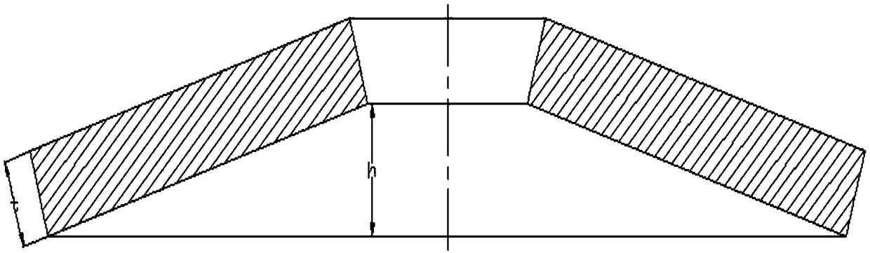
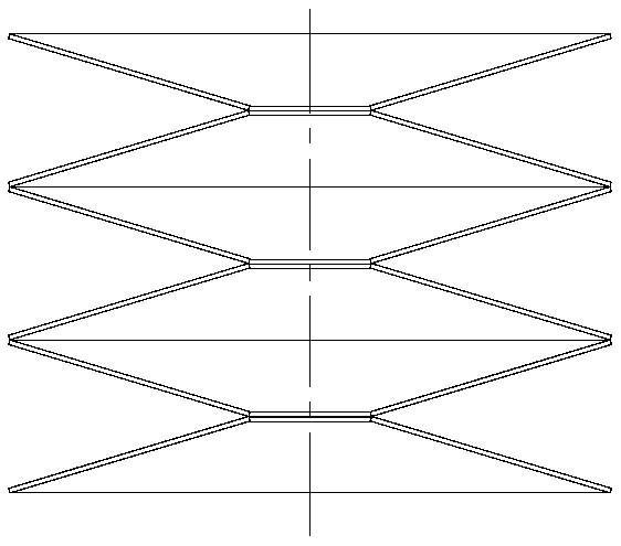
[0040] This embodiment is used for self-pressurized fuel tanks for space propulsion, such as Image 6 As shown, it includes: shell 1, piston 2, upper cover 3, lead screw and nut mechanism 4, motor-bevel gear set 5, disc spring set 6, pipe 7, one end of the shell is externally connected to the pipe, and the other end is connected to the lead screw and nut mechanism , the upper cover 3, the disc spring group 6, and the piston 2 are arranged in sequence from top to bottom inside the housing, the housing located in the lower space of the piston is filled with liquid fuel, and the disc spring group is arranged between the piston and the upper cover, and the disc The upper end of the disc spring group 6 is close to the lower end surface of the upper cover, and the lower end of the disc spring group 6 is close to the bottom surface of the inner wall of the piston 2; a lead screw nut mechanism is connected between the upper cover and the shell, and the lead screw nut mechanism is simul...

Embodiment 2

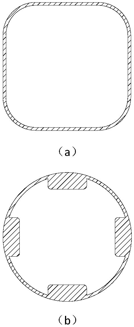
[0045] The motor-bevel gear set of the fuel tank of this embodiment is installed in the loam cake, and the installation method is exactly the same as that in embodiment 1; Difference with embodiment 1 is that piston and loam cake (referring to Figure 9 ). The present embodiment piston (see Figure 10 ) should fit tightly against the non-circular inner wall of the housing, and a circular guide post should be provided on the piston to accommodate the disc spring pack. cover (see Figure 11 ) has a concave circular sleeve set on the circular guide post of the piston, and the upper edge of the upper cover should also be close to the non-circular inner wall of the shell. The outer diameter of the concave circular sleeve is greater than the radius of the disc spring.

Embodiment 3

[0047] The present embodiment fuel tank (referring to Figure 12 ) The motor-bevel gear set is installed in the upper cover, and the installation method is exactly the same as in Embodiment 2; the installation method and function of the screw nut are also exactly the same as in Embodiment 2. piston (see Figure 13 ) will be close to the non-circular inner wall of the shell, the piston is concave, and the piston must have a circular guide post simultaneously, and a disc spring group is installed on the circular guide post. cover (see Figure 14 ) has a concave circular sleeve to be enclosed within on the circular guide post of the piston, and the difference with embodiment 2 is that the upper edge of the loam cake will be close to the concave inner wall of the piston. The outer diameter of the concave circular sleeve is greater than the radius of the disc spring.


PUM


Abstract

The invention provides a self-pressurized fuel tank used for space propulsion. The fuel tank comprises a shell, a piston, an upper cover, a screw nut mechanism, a motor-cone gear set, a disc spring group and a pipeline, wherein one end of the shell is externally connected with the pipeline, the other end of the shell is connected with the screw nut mechanism, the inner portion of the shell is provided with the upper cover, the disc spring group and the piston from top to bottom in sequence, the position, located in lower space of the piston, of the shell is filled with liquid fuel, the disc spring group is arranged between the piston and the upper cover, the upper end of the disc spring group is closely next to the lower end face of the upper cover, and the lower end of the disc spring group is closely next to the bottom face of the inner wall of the piston; the screw nut mechanism is connected between the upper cover and the shell, the screw nut mechanism also is connected to the motor-cone gear set, and the motor-cone gear set drives the screw nut mechanism to rotate; the outer surface of the piston is in contact with the inner surface of the shell. The fuel tank uses the elasticforce of disc springs as power to extrude fuel, and is simple in structure and conductive to the attitude control of a spacecraft.

Description

technical field [0001] The invention belongs to the field of aerospace, in particular to a self-pressurized fuel tank for space propulsion, which is mainly used for a spacecraft orbit attitude control power system. Background technique [0002] Orbit and attitude control power system is one of the important components of spacecraft, mainly used for attitude control and stabilization of various spacecraft, orbit change and orbit correction, space rendezvous and docking, and it can also brake and decelerate for re-entry into the atmosphere Provide control. The gas generator is the most important part of the orbit attitude control power system. They generate thrust by ejecting gas, and then adjust the attitude of the spacecraft. The outer space environment is zero gravity and zero pressure, so for the orbit attitude control power system using liquid fuel, the spacecraft needs to use its own power to deliver fuel to the gas generator. Most of the early orbit attitude control p...

Claims


Application Information

Patent Timeline
Patent Type & Authority Applications(China)
IPC IPC(8): B64G1/22B64G1/40
CPCB64G1/22B64G1/402B64G1/245
Inventor 刘远鹏
Owner HEBEI UNIV OF TECH
Why Eureka
Try Eureka