
Treatment system for heavy metal wastewater

A waste water treatment system, heavy metal technology, applied in the direction of water/sewage treatment, adsorption water/sewage treatment, water/sludge/sewage treatment, etc., can solve the problems of uneven particle size of activated carbon, low efficiency of activated carbon crushing, etc. Uniformity, innovative design, and efficiency-enhancing effect

Inactive Publication Date: 2019-03-12
孙勇
View PDF4 Cites 5 Cited by
  • Summary
  • Abstract
  • Description
  • Claims
  • Application Information

AI Technical Summary

Problems solved by technology

[0005] In order to make up for the deficiencies of the prior art and to solve the problems of low efficiency of activated carbon crushing and uneven size of activated carbon particles in the prior art, the present invention proposes a heavy metal wastewater treatment system

Method used


Image

  • Treatment system for heavy metal wastewater
  • Treatment system for heavy metal wastewater
  • Treatment system for heavy metal wastewater

Examples


Embodiment approach

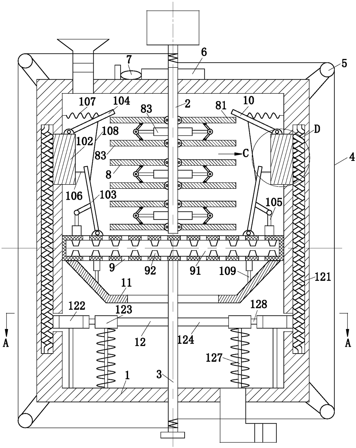
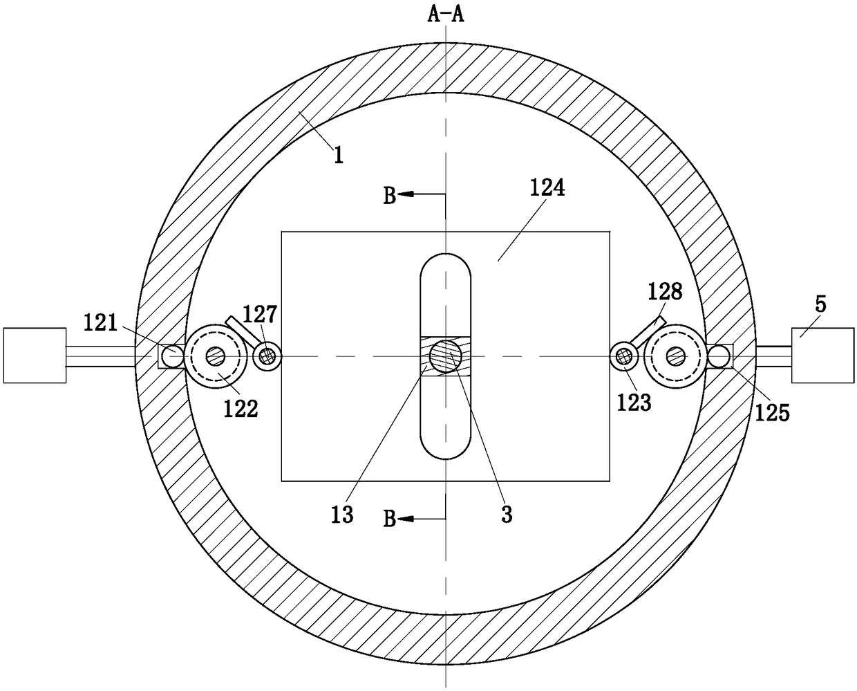
[0033] As a specific embodiment of the present invention, a filter unit 12 is provided below the guide ring 11, and the filter unit 12 is used to filter the activated carbon again; the filter unit 12 includes a No. 2 spring 121, a gear 122, a rotating The wheel 123 and the filter screen 124; the side wall of the working chamber 1 is provided with a No. 2 hollow cavity 125, the No. 2 hollow cavity 125 is located outside the chute 101, and the side above the No. The chute 101 is connected, the side below the No. 2 hollow cavity 125 is provided with an opening, and the side of the slider 102 away from the elastic cloth 106 is fixed with a conical convex tooth 126; the No. 2 spring 121 is located in the No. 2 hollow cavity body 125, and the end of the No. 2 spring 121 is rotatably connected to the No. 2 hollow cavity 125; the conical protruding teeth 126 are located between the adjacent spring coils of the No. 2 spring 121 and are in contact with the No. 2 spring 121, the cone The...

specific Embodiment approach

[0034] As a specific embodiment of the present invention, the part of the No. 2 rotating rod 3 located in the through hole of the filter screen 124 is sleeved with a slip ring 13, an elastic film 131 is arranged between the slip ring 13 and the through hole, and the elastic film 131 One end is fixedly connected with the slip ring 13, and the other end is fixedly connected with the through hole; in the present invention, by setting the slip ring 13 and the elastic film 131, when the filter screen 124 moves up and down in the horizontal direction, the elastic film 131 is stretched and blocked The gap between the slip ring 13 and the through hole prevents the activated carbon from falling out of the through hole of the filter screen 124, resulting in poor filtration of the activated carbon.

[0035] When the activated carbon falls from the filter ring 9, it enters into the guide ring 11. The guide ring 11 is used to receive the pulverized activated carbon particles to prevent the ...


PUM


Abstract

The invention belongs to the technical field of wastewater treatment, and particularly discloses a treatment system for heavy metal wastewater. The treatment system comprises a motor, a working chamber, a charging hole, a discharge hole and a controller, wherein the motor is located in the middle of the top of the working chamber; an output end of the motor is fixedly connected with a 1# rotatingrod; one end, which is far away from an output shaft of the motor, of the 1# rotating rod penetrates through the top of the working chamber and extends to the interior of the working chamber; the bottom of the working chamber is provided with a 2# rotating rod; one end of the 2# rotating rod penetrates through the bottom of the working chamber and extends to the interior of the working chamber; rigid ropes are wound on both the output end of the motor and the 2# rotating rod; further, the direction of turning of the rigid rope on the output end of the motor is opposite to that of the rigid rope on the 2# rotating rod; and the working chamber is internally provided with a 1# crushing unit, a 2# crushing unit, a filtering ring and a filtering unit. The treatment system is simple in structure, novel in design and high in action consistency; and the efficiency of crushing activated carbon is improved.

Description

technical field [0001] The invention belongs to the technical field of wastewater treatment, in particular to a heavy metal wastewater treatment system. Background technique [0002] Heavy metal wastewater refers to wastewater containing heavy metals discharged from industrial production processes such as mining and metallurgy, machinery manufacturing, chemical industry, electronics, and instrumentation; heavy metal (such as cadmium, nickel, mercury, zinc, etc.) wastewater is the most serious environmental pollution and human. It is one of the most harmful industrial wastewater, and activated carbon has the properties of chemical adsorption, catalytic oxidation and reduction, and can effectively remove some metal ions in wastewater. In order to increase the surface area of ​​activated carbon, to achieve a good effect of removing heavy metals. [0003] There are also some devices for the treatment of heavy metal wastewater in the prior art. For example, a Chinese patent with...

Claims


Application Information

Patent Timeline
Patent Type & Authority Applications(China)
IPC IPC(8): C02F1/28B02C23/16B02C21/00C02F101/20
CPCB02C21/00B02C23/16C02F1/283C02F2101/20
Inventor 孙勇吴爱兵
Owner 孙勇
Learn More