
Fabricated prefabricated reinforced concrete beam connection joint and construction method thereof

A technology of reinforced concrete beams and precast concrete, which is applied to buildings and building structures, etc., can solve the problems of high assembly rate, poor ductility deformation capacity of dry connecting beams, and low seismic capacity, so as to improve seismic performance and strengthen ductile deformation. Ability and seismic performance, practical effect

Pending Publication Date: 2019-03-12
CHANGAN UNIV
View PDF0 Cites 9 Cited by
  • Summary
  • Abstract
  • Description
  • Claims
  • Application Information

AI Technical Summary

Problems solved by technology

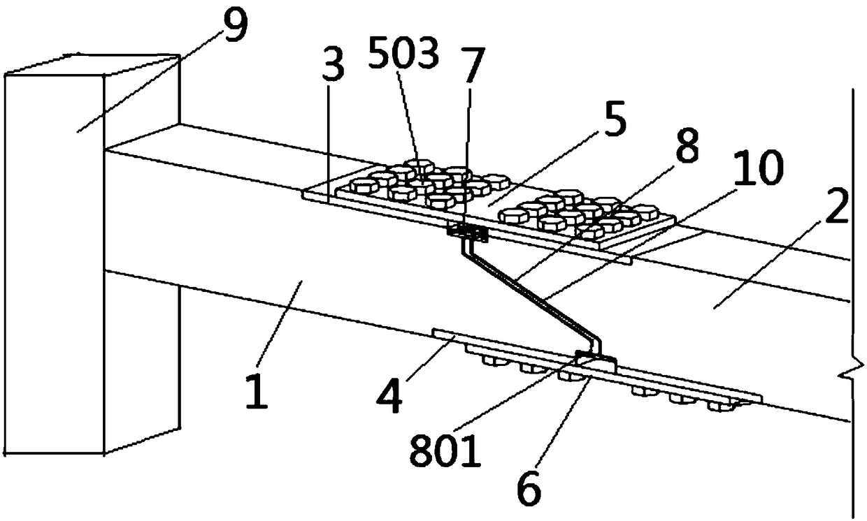
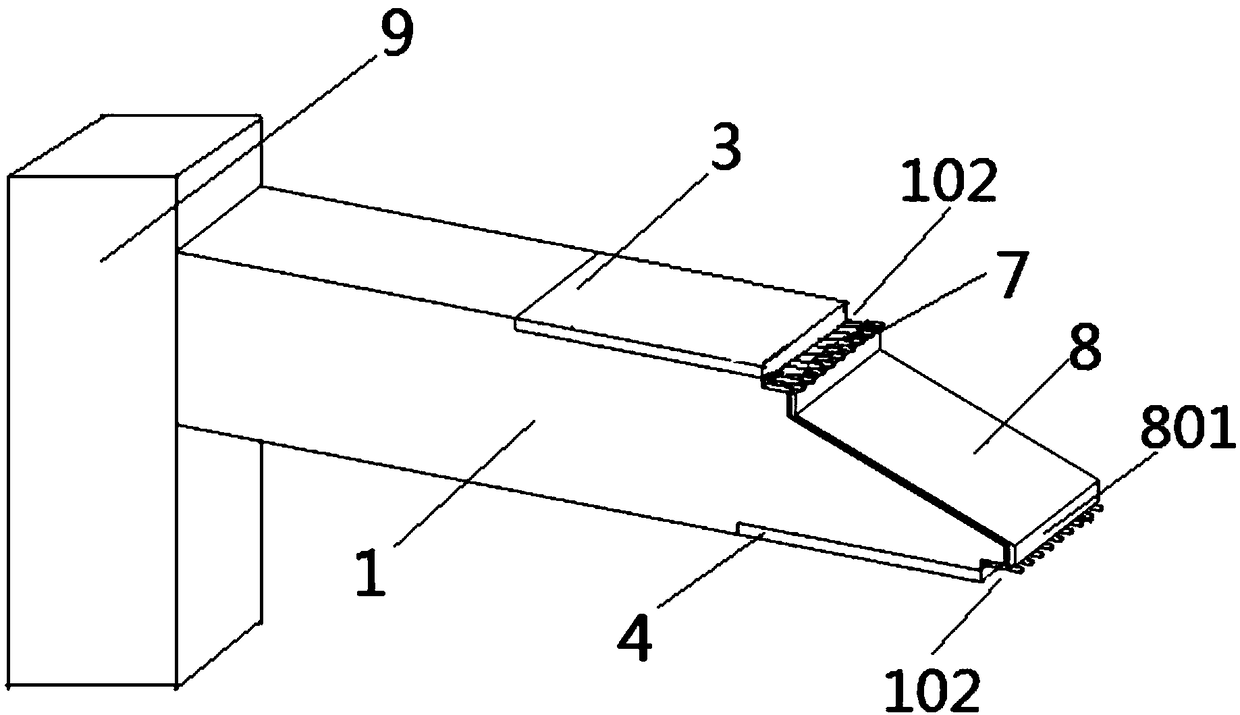
[0004] In order to solve the above problems, the object of the present invention is to propose a connection node of an assembled prefabricated reinforced concrete beam and its construction method, which realizes three-layer energy consumption through structural design, and solves the problem of poor ductility and deformation capacity between dry connection beams and The problem of low seismic capacity; at the same time, the connection node is easy to replace after the earthquake damage, and the assembly is convenient without special construction support, and the assembly rate is high

Method used


Image

  • Fabricated prefabricated reinforced concrete beam connection joint and construction method thereof
  • Fabricated prefabricated reinforced concrete beam connection joint and construction method thereof
  • Fabricated prefabricated reinforced concrete beam connection joint and construction method thereof

Examples


Embodiment

[0064] A construction method for a connection node of an assembled prefabricated reinforced concrete beam, comprising the following steps:

[0065] Step 1, making a convex precast concrete beam and a convex precast concrete beam.

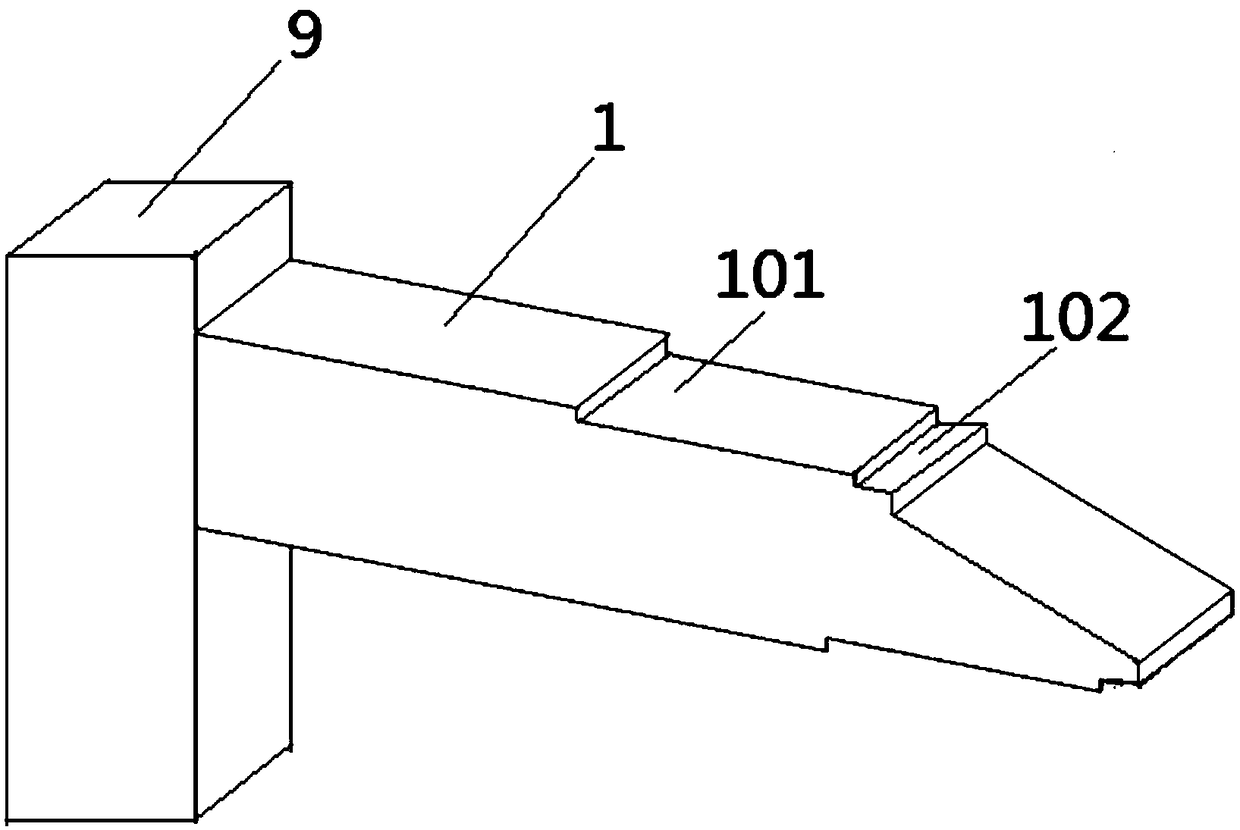
[0066] Step 2, embed the upper pre-embedded steel plate and the lower pre-embedded steel plate in the first notch and the second notch; specifically, embed the upper pre-embedded steel plate and the lower pre-embedded steel plate into the corresponding notch, so that the upper pre-embedded steel plate The upper end surface of the steel plate is flush with the upper end surfaces of the lower convex precast concrete beam and the upper convex precast concrete beam, so that the lower end surface of the lower pre-embedded steel plate is flush with the lower end surfaces of the lower convex precast concrete beam and the upper convex precast concrete beam. The connecting steel plate is pre-embedded on the slope surface of the connecting side wall of the do...


PUM


Abstract

The invention discloses a fabricated prefabricated reinforced concrete beam connection joint and a construction method thereof. The connection joint comprises a lower convex prefabricated concrete beam and an upper convex prefabricated concrete beam. First concave openings are formed in the upper and lower end faces of the connection side wall of the lower convex prefabricated concrete beam, and second concave openings are correspondingly formed in the upper and lower end faces of the connection side wall of the upper convex prefabricated concrete beam; upper prefabricated steel plates and lower prefabricated steel plates are arranged inside the first concave openings and the second concave openings; the upper and lower prefabricated steel plates are correspondingly connected with upper and lower reinforcing steel plates; the connection side walls of the two beams are provided with a third concave opening and a fourth concave opening respectively, and load-bearing bars are correspondingly and transversely arranged inside the third concave opening and the fourth concave opening. The method comprises the steps of manufacturing the two beams, prefabricating the steel plates, performing butt connection on the two beams, and connecting the load-bearing bars inside the two beams. Due to the structural design, three-layer energy dissipation is achieved, and the problems that the shockresistance is poor and the ductility deformability is poor between dry type connection beams are solved; after seismic damage, replacement is easy, assembling is convenient, and the assembling rate is high.

Description

technical field [0001] The invention relates to the technical field of construction engineering, in particular to a connection node of an assembled prefabricated reinforced concrete beam and a construction method thereof. Background technique [0002] Due to its short construction period, simple construction, and material saving, prefabricated buildings are an important structural form to promote construction industrialization and green buildings, and play an important role in the future construction industry. [0003] The connection mode of concrete prefabricated structural nodes is divided into wet connection and dry connection. For wet joint connection, the beam-column components are manufactured in the factory in advance, and then assembled and hoisted after being transported to the site, and concrete is poured on the beam-column joints, and the monolithic structure is poured after completion. Since the concrete at the joints is solidified after the prefabricated concre...

Claims


Application Information

Patent Timeline
IPC IPC(8): E04B1/21
CPCE04B1/21E04B1/215
Inventor 叶艳霞王宗彬高大伟刘继磊彭琼武韩伟
Owner CHANGAN UNIV
Learn More