
Intelligent window changing illumination angle

A lighting angle and smart window technology, which is applied in the field of smart windows, can solve the problems of damage to the external connection components of the window, reduced device performance, and weak device flexibility, etc., to achieve improved flexibility, enhanced connection performance, and uniform force Effect

Pending Publication Date: 2019-03-12
东莞市同窗智能科技有限公司
View PDF0 Cites 1 Cited by
  • Summary
  • Abstract
  • Description
  • Claims
  • Application Information

AI Technical Summary

Problems solved by technology

[0004] The purpose of the present invention is to provide a smart window that can change the angle of illumination to solve the problem that the existing smart windows proposed in the background technology are installed in high-rise buildings during use, and it is difficult to adjust the angle of the window to block the sun according to the intensity of light. Changing the operation makes the flexibility of the device not strong, resulting in a decline in the working performance of the device, and the device is not easy to self-close itself according to the wind direction and wind speed, resulting in the problem that the connecting components on the outside of the window are prone to damage

Method used


Image

  • Intelligent window changing illumination angle
  • Intelligent window changing illumination angle
  • Intelligent window changing illumination angle

Examples


Embodiment Construction

[0027] The following will clearly and completely describe the technical solutions in the embodiments of the present invention with reference to the accompanying drawings in the embodiments of the present invention. Obviously, the described embodiments are only some, not all, embodiments of the present invention. Based on the embodiments of the present invention, all other embodiments obtained by persons of ordinary skill in the art without making creative efforts belong to the protection scope of the present invention.

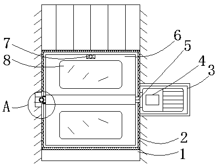
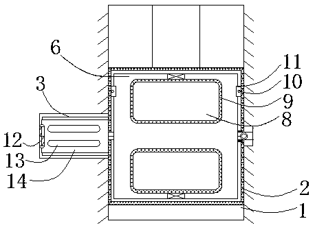
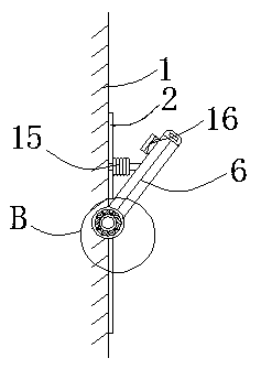
[0028] see Figure 1-6 , the present invention provides a technical solution: a smart window that can change the illumination angle, including a base body 1, a window frame 2, a protective cover 3, a servo motor 4, a rotating shaft 5, a movable window 6, an illumination sensor 7, tempered glass 8, Rubber strip 9, bolt 10, limit block 11, door shaft 12, strip vent 13, movable door 14, spring 15, bump 16, support plate 17, wind direction and speed sensor 18, bea...


PUM


Abstract

The invention relates to an intelligent window changing an illumination angle. The intelligent window comprises a base body, a movable window and an illumination sensor, wherein a window frame is arranged on the inner side of the base body, a protective cover is connected to the right side of the window frame, the base body is connected with the window frame through a screw, and the window frame is in welding connection with the protective cover; the movable window is movably arranged on the inner side of the window frame, and a rotating shaft penetrates through the movable window, and is engaged with the movable window. The intelligent window changing the illumination angle has the advantages that by arranging the window frame, the movable window, the rotating shaft, a servo motor and theillumination sensor, the illumination sensor is embedded into the inner side of the top of the outer wall of the movable window, when the movable window is in the starting state, natural illuminationis subjected to illumination intensity detection through the illumination sensor, and when the illumination intensity is higher than a preset value, the servo motor is started to drive the rotating shaft to rotate, the movable window on the outer side of the illumination sensor rotates together, the illumination angle of natural illumination for the inner side of the base body is changed, and theflexibility of the device is improved.

Description

technical field [0001] The invention relates to the technical field of smart windows, in particular to a smart window capable of changing the illumination angle. Background technique [0002] With the increasing emphasis on environmental protection and energy saving, great progress has been made in the rational use of energy and the research and development of energy-saving products. Under this background, in the early 1980s, C. M. Lampert, C. G. Granqvist et al. first proposed to apply electrochromic materials to energy-saving lighting systems such as buildings, automobiles, and airplanes to form a "smart window" that can dynamically adjust the transmittance of solar radiation. In recent years, research on smart windows and Application has always been a research hotspot. [0003] When the existing smart windows are installed in high-rise buildings, it is difficult to change the angle of the window to block the sun according to the light intensity, which makes the device...

Claims


Application Information

Patent Timeline
IPC IPC(8): E06B3/38E06B1/36E06B5/11E06B7/02E06B1/60E05F15/70E05F15/73E05F15/611E05F15/71E05C19/00H02K5/04
CPCE06B3/38E05C19/00E05F15/611E05F15/70E05F15/71E05F15/73E05F2015/765E05Y2900/148E06B1/36E06B1/60E06B5/11E06B7/02E06B2003/403H02K5/04
Inventor 黄高欢
Owner 东莞市同窗智能科技有限公司
Learn More