Drying device

The technology of drying device and drying cylinder is applied in the directions of drying, drying machine, drying gas arrangement, etc., which can solve the problems of different size and moisture of straw, not meeting people's requirements for use, and not enough to meet the requirements of use, etc. Improve drying effect, simple structure and energy saving effect

Pending Publication Date: 2019-03-12
安徽翔丰再生能源有限公司
View PDF18 Cites 0 Cited by
  • Summary
  • Abstract
  • Description
  • Claims
  • Application Information

AI Technical Summary

Problems solved by technology

[0002] With the development of society, people's demand for energy is increasing, coupled with the deterioration of the environment, people urgently need a clean and renewable energy, so people discovered biomass energy, and my country's biomass energy is very rich For example, the amount of straw resources is 312 million tons. People have invented some machines for better use of straw, including drying devices. With the rapid development of science and technology, people have higher and higher requirements for drying devices. , leading to the existing drying device can not meet people's use requirements;
[0003] There are certain disadvantages in the use of the existing drying device. First, the size and moisture content of the primary crushed straw are different. The drying of the existing drying device is uneven during drying, which affects the subsequent processing. Moreover, the current Some drying devices have a relatively long drying time, low drying efficiency, waste of resources, and do not meet people's requirements. For this reason, we propose a drying device

Method used


Image

  • Drying device
  • Drying device
  • Drying device

Examples


Embodiment 1

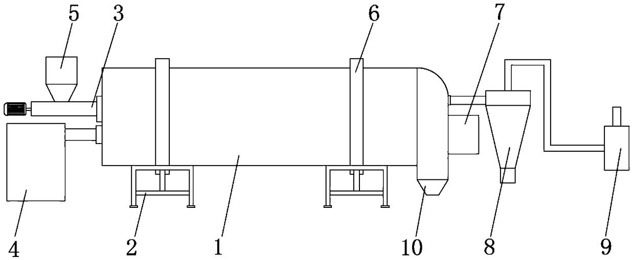
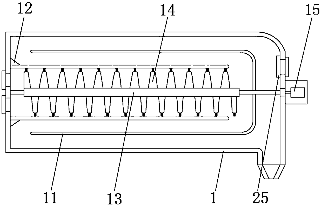
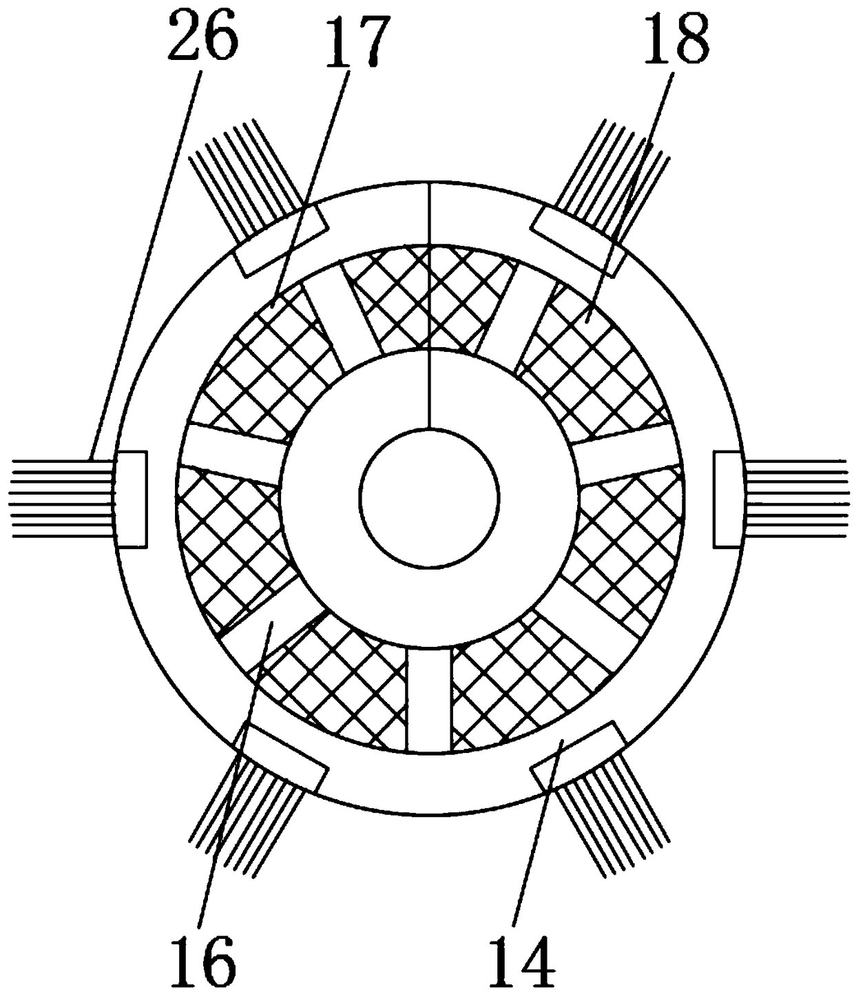
[0029] Such as Figure 1-5 As shown, a drying device includes a drying cylinder 1, a support frame 2 is fixedly installed on the outer surface of the lower end of the drying cylinder 1, a screw feeder 3 and a hot blast stove 4 are arranged on one side of the drying cylinder 1, and The spiral feeder 3 is located above the hot blast stove 4, the outer surface of the spiral feeder 3 is provided with a feeding barrel 5 near one end, the outer surface of the drying barrel 1 is fixedly equipped with a fixing ring 6, and the drying barrel 1 is far away from the An electrical box 7 is fixedly installed in the middle of the outer surface of one end of the hot blast stove 4, and the side of the electrical box 7 away from the drying cylinder 1 is provided with a cyclone dust collector 8 and an induced draft fan 9, and the cyclone dust collector 8 is located on the side of the induced draft fan 9 One side of the electrical box 7 is located at the lower outer surface of the drying cylinder...

Embodiment 2

[0033] Such as Figure 1-5 As shown, a drying device includes a drying cylinder 1, a support frame 2 is fixedly installed on the outer surface of the lower end of the drying cylinder 1, a screw feeder 3 and a hot blast stove 4 are arranged on one side of the drying cylinder 1, and The spiral feeder 3 is located above the hot blast stove 4, the outer surface of the spiral feeder 3 is provided with a feeding barrel 5 near one end, the outer surface of the drying barrel 1 is fixedly equipped with a fixing ring 6, and the drying barrel 1 is far away from the An electrical box 7 is fixedly installed in the middle of the outer surface of one end of the hot blast stove 4, and the side of the electrical box 7 away from the drying cylinder 1 is provided with a cyclone dust collector 8 and an induced draft fan 9, and the cyclone dust collector 8 is located on the side of the induced draft fan 9 One side of the electrical box 7 is located on the outer surface of the lower end of the dryi...

Embodiment 3

[0038] Such as Figure 1-5As shown, a drying device includes a drying cylinder 1, a support frame 2 is fixedly installed on the outer surface of the lower end of the drying cylinder 1, a screw feeder 3 and a hot blast stove 4 are arranged on one side of the drying cylinder 1, and The spiral feeder 3 is located above the hot blast stove 4, the outer surface of the spiral feeder 3 is provided with a feeding barrel 5 near one end, the outer surface of the drying barrel 1 is fixedly equipped with a fixing ring 6, and the drying barrel 1 is far away from the An electrical box 7 is fixedly installed in the middle of the outer surface of one end of the hot blast stove 4, and the side of the electrical box 7 away from the drying cylinder 1 is provided with a cyclone dust collector 8 and an induced draft fan 9, and the cyclone dust collector 8 is located on the side of the induced draft fan 9 One side of the electrical box 7 is located on the outer surface of the lower end of the dryin...


PUM


Abstract

The invention discloses a drying device. The drying device comprises a drying barrel; supporting frames are fixedly mounted on the outer surface of the lower end of the drying barrel; a helical loaderand a hot blast furnace are arranged on one side of the drying barrel; the helical loader is located above the hot blast furnace; a loading barrel is arranged in the position, close to one end, of the outer surface of the helical loader; a fixing ring is fixedly mounted on the outer surface of the drying barrel; an electrical box is fixedly mounted in the middle of the outer surface of one end, far away from the hot blast furnace, of the drying barrel; and a cyclone dust collector and an induced draft fan are arranged on one side, far away from the drying barrel, of the electric box. By the aid of the drying device, firstly, the running distance of crops in the drying barrel can be increased, so that the drying effect of the drying barrel is improved, the crops can be dried more evenly, people can process the crops conveniently later, finally, the drying process of straw is accelerated, the efficiency of the drying device is improved, and the drying device has the better use prospect.

Description

technical field [0001] The invention relates to the field of drying devices, in particular to a drying device. Background technique [0002] With the development of society, people's demand for energy is increasing, coupled with the deterioration of the environment, people urgently need a clean and renewable energy, so people discovered biomass energy, and my country's biomass energy is very rich For example, the amount of straw resources is 312 million tons. People have invented some machines for better use of straw, including drying devices. With the rapid development of science and technology, people have higher and higher requirements for drying devices. , leading to the existing drying device can not meet people's use requirements; [0003] There are certain disadvantages in the use of the existing drying device. First, the size and moisture content of the primary crushed straw are different. The drying of the existing drying device is uneven during drying, which affects...

Claims


Application Information

Patent Timeline
Patent Type & Authority Applications(China)
IPC IPC(8): F26B17/20F26B21/00F26B25/00F26B25/04B08B1/00
CPCF26B17/20F26B21/001F26B25/007F26B25/04F26B2200/02B08B1/12
Inventor 陈向峰
Owner 安徽翔丰再生能源有限公司
Why Eureka
Try Eureka